

Two wheel drive bicycle with a shock-absorbing front fork
a two-wheel drive, front fork technology, applied in cycle equipment, transportation and packaging, gearing, etc., can solve the problems of reducing the traction and climbing ability of the bicycle, reducing the traction and climbing ability, and reducing the traction of the bicycl
- Summary
- Abstract
- Description
- Claims
- Application Information
AI Technical Summary
Benefits of technology
Problems solved by technology
Method used
Image

Examples
first embodiment
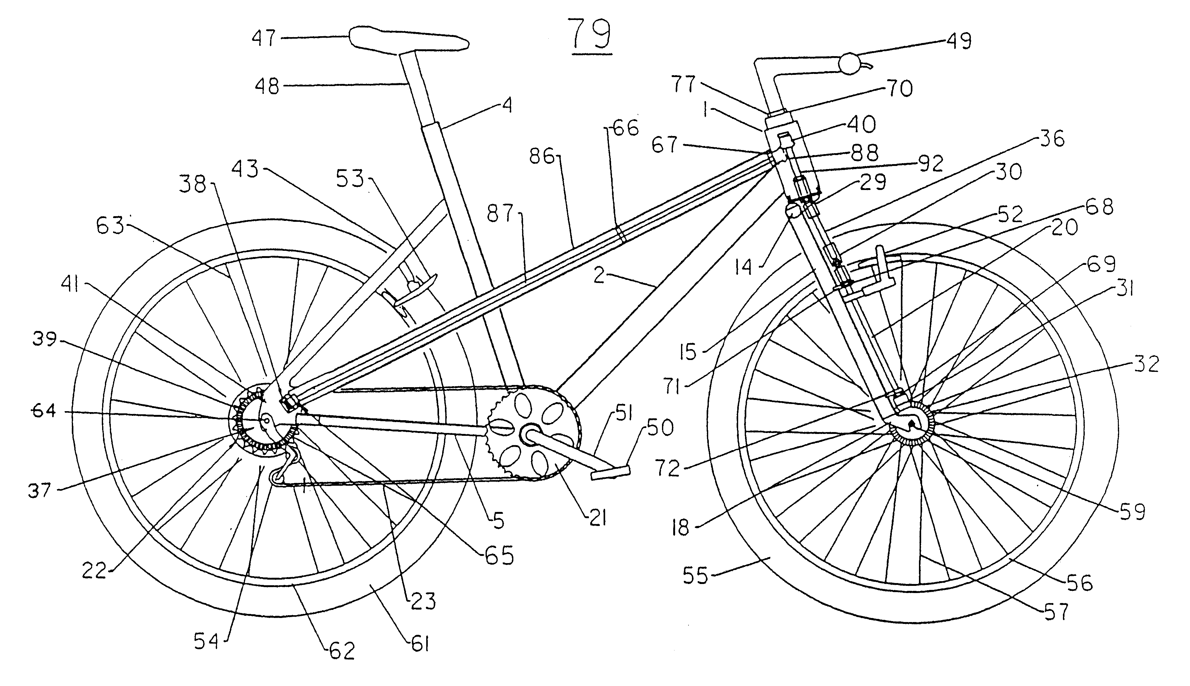
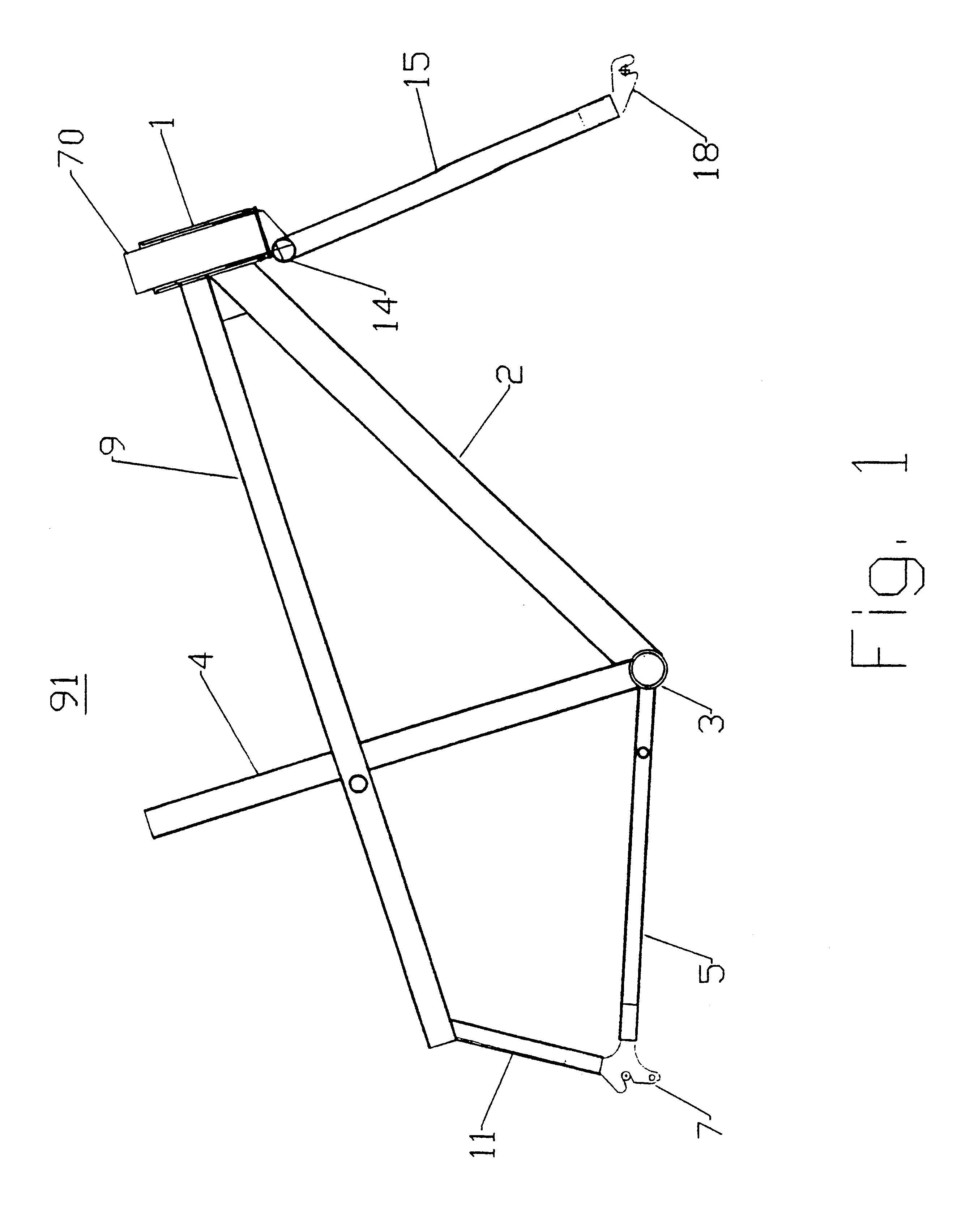
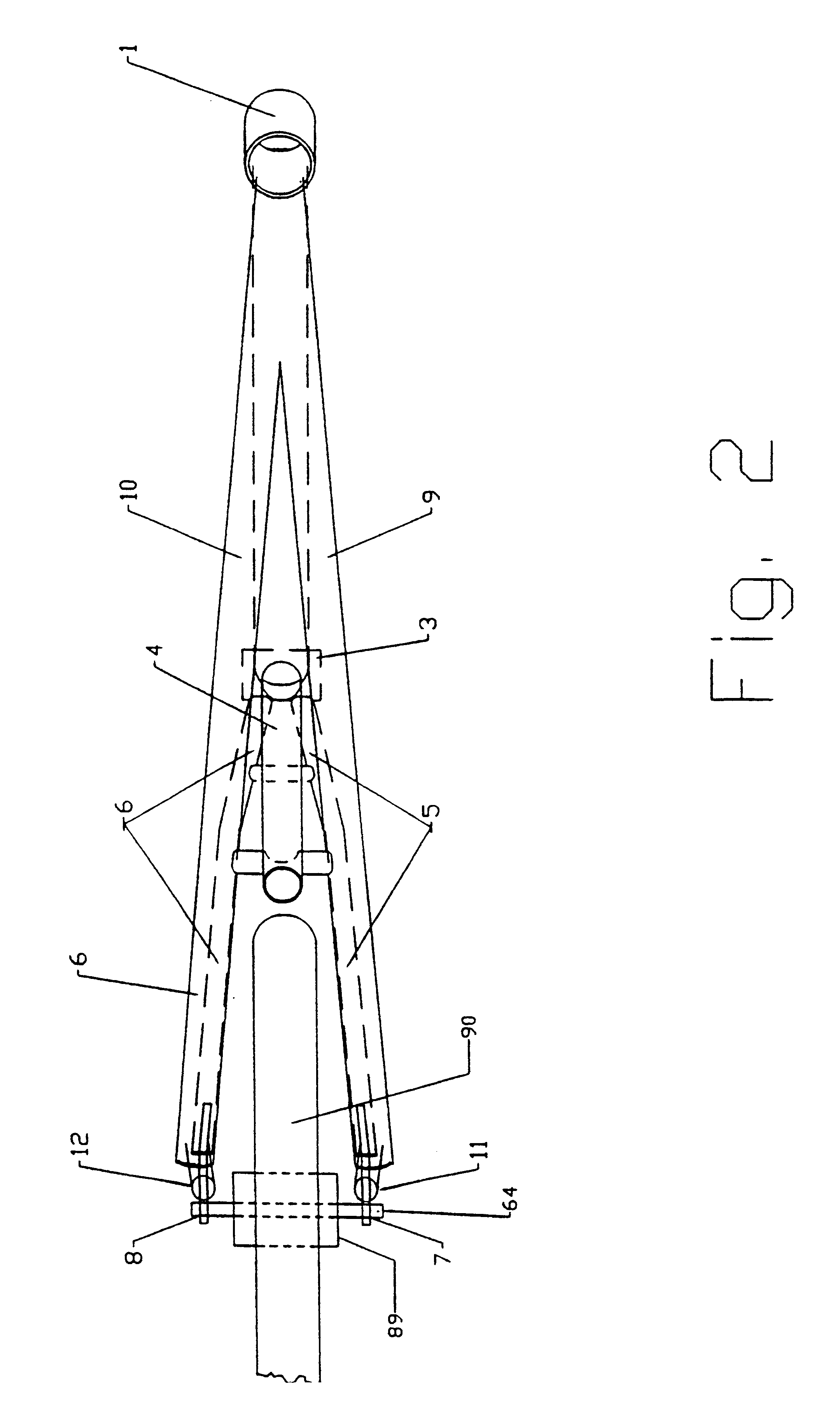
Referring now to the drawings of the frame, FIGS. 1, 2, 3, 9, and 12 show the frame design of the two wheel drive bicycle 78. The frame 91 comprises a single head tube 1, connecting a single down tube 2, which connects at the crank tube 3, with the seat tube 4, a right chain stay 5, a left chain stay 6 which then terminate with a right rear dropout 7 and a left rear dropout 8, respectively. The main drive tube 9 and the main frame tube 10 form a dual horizontal tube construction beginning at the head tube 1 at the front of the frame 91 and extending rearward where the main drive tube 9 connects to a right rear support tube 11 and the main frame tube connects to a left rear support tube 1. The right rear support tube 11 connects the rear end of the main drive tube 9 with the right chain stay 5 at the right rear drop out 7 and the left rear support tube 12 connects the rear end of the main frame tube 10 with the left chain stay 6 at the left rear drop out 8. As is well known in the ar...
embodiment 78
FIGS. 3 and 9 illustrate aspects of the bicycle 78 design which encompass the front fork assembly descending from the head tube 1. The front fork assembly begins with a neck tube 70 located within the head tube 1 and connecting at one end with a front fork post support 14. The front fork post support 14 connects with the upper ends of the right front fork member 15 and the left front fork member 16 which pass along the sides of the front tire 17. The right front fork member 15 terminates at the right front dropout 18 and the left front fork member 16 terminates at the left front dropout 19. The front wheel 17 mounts rotationally on the front axle 59 between the right front dropout 17 and left front dropout 18. The right fork member 15 holds the front drive shaft 20 in the present The front brakes 52 are mounted on the right front fork member 15 and the left front fork member 16 as is well known in the art.
The precision design of the front fork assembly is critical for proper power ...
second embodiment
OF THE INVENTION
FIGS. 10, 11 and 13 illustrate aspects of a two wheel drive bicycle 79 wherein the modified drive sprocket 34, the second drive chain 24, the second drive sprocket 25 and first rear drive system bracket 45 and the second rear drive system bracket 46 described in the first embodiment of the two wheel drive bicycle 78 are replaced by a rear wheel bevel gear 37 and a drive shaft pinion gear 38 to power the front wheel in an alternative manner.
In the second embodiment of the two wheel drive bicycle 79, the power transmitted to the rear drive sprockets 22 from the pedal crank shaft 51 through the chain 23 is transferred to the rear wheel bevel gear 37 mounted circumferentially on the outer region of the rear drive sprockets 22 to result in simultaneous turning of the rear drive sprockets 22 and the rear wheel bevel gear 37. The rear wheel bevel gear 37 meshes directly with a drive shaft pinion gear 38 to transfer power directly to the straight main drive shaft 87. As show...
PUM
 Abstract
Description
Claims
Application Information