Electrostatic device for correcting chromatic aberration in a particle-optical apparatus

a particle-optical apparatus and electrostatic technology, applied in the field of particle-optical apparatuses, can solve the problems of limiting the resolution of the particle-optical apparatus to substantially the same extent, the deflecting effect of the particle-optical apparatus is negligible, and the configuration disclosed in the article by scherzer cannot be simply used in the particle-optical apparatus. , to achieve the effect of significantly reducing the chromatic magnification error

Inactive Publication Date: 2001-02-06
FEI CO
View PDF1 Cites 33 Cited by
  • Summary
  • Abstract
  • Description
  • Claims
  • Application Information

AI Technical Summary

Benefits of technology

The position of the variable K.sub.y in the expression (31) contains the value 0 in the expression (44), so that the factor of ....

Problems solved by technology

However, in the cited article it is assumed that for the rays of deviating energy this distance from the optical axis is so small that the deflecting effect thereof is negligibly small.
Generally speaking, the configuration disclosed in the article by Scherzer cannot be simply used in a particle-optical apparatus.
This effect would then introduce a further error, the so-called chromatic magnification error, which would limit the resolution of the particle-optical apparatus to substantially the same extent as the already described chromatic aberration.
In the following sections III-2-a and III-2-b it will be demonstrated that the use of the method disclosed in the cited article by Scherzer in an elec...

Method used


Image

  • Electrostatic device for correcting chromatic aberration in a particle-optical apparatus
  • Electrostatic device for correcting chromatic aberration in a particle-optical apparatus
  • Electrostatic device for correcting chromatic aberration in a particle-optical apparatus

Examples


Embodiment Construction

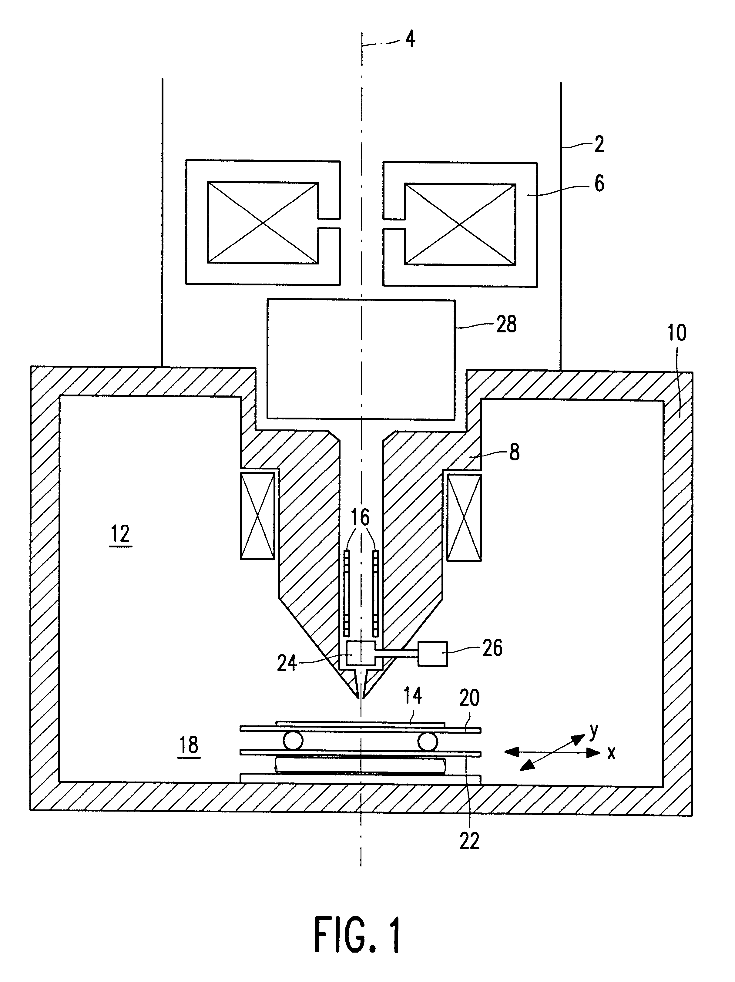
FIG. 1 shows a particle optical instrument in the form of a part of a column 2 of a scanning electron microscope (SEM). As is usual, a beam of electrons is emitted by an electron source in this instrument (not shown in the Figure), said beam traveling along the optical axis 4 of the instrument. The electron beam can traverse one or more electromagnetic lenses, such as the condensor lens 6, after which it reaches the objective lens 8. This lens, being a so-called monopole lens, forms part of a magnetic circuit which is also formed by the wall 10 of the specimen chamber 12. The objective lens 8 is used to form an electron beam focal spot whereby the specimen 14 is scanned. Scanning takes place by moving the electron beam across the specimen in the x direction as well as the y direction by means of scan coils 16 which are provided in the objective lens 8. The specimen 14 is arranged on a specimen table 18 which includes a carrier 20 for the x displacement and a carrier 22 for the y dis...


PUM


Abstract

Electron-optical rotationally symmetrical lenses inevitably suffer from chromatic aberration which often determines the resolution limit at low acceleration voltages. This lens defect cannot be eliminated by compensation by means of rotationally symmetrical fields. In order to improve the resolution nevertheless, it has already been proposed to correct the chromatic aberration by means of a corrector (28) provided with two correction elements (34, 40). Each correction element consists of a number of quadrupole fields. Using the known corrector, it has been found that the chromatic magnification error is inadmissibly high. In order to solve this problem, the correction elements in the corrector according to the invention are provided with at least five layers of electrodes (60-a, 60-b, 60-c, 60-d) which produce quadrupole fields. Because of the strong periodicity of the electron paths in the correcting quadrupole fields, the chromatic magnification error is limited sufficiently (or even reduced to zero) so as to allow the use of the corrector for practical purposes.

Description

I FIELD OF THE INVENTIONThe invention relates to a particle-optical apparatus which includes:a particle source for emitting a beam of electrically charged particles which travel along an optical axis of the apparatus in order to expose an object, to be irradiated in the apparatus, by means of the particle beam,a focusing lens for focusing the beam of electrically charged particles,and a correction device for correcting the chromatic aberration of the focusing lens,which correction device includes correction elements, each of which is provided with electrodes for producing electric quadrupole fields, said electrodes being arranged in successive layers along the optical axis, the quadrupole fields produced by the electrodes in the layers being rotated through an angle of substantially 90.degree. about the optical axis relative to the quadrupole field produced by the electrodes in an adjacent layer.The invention also relates to a correction device for use in such an apparatus, and to a...

Claims


Application Information

Patent Timeline
IPC IPC(8): H01J37/153H01J37/04H01J37/12
CPCH01J37/153H01J2237/04924H01J2237/1534
Inventor HENSTRA, ALEXANDERKRIJN, MARCELLINUS P. C. M.
Owner FEI CO
Why Eureka
Try Eureka