

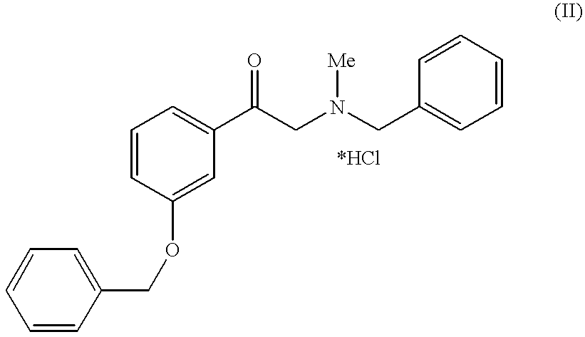
Method for preparing of L-phenylephrine hydrochloride
a technology of l-phenylephrine and hydrochloride, which is applied in the field of preparing l-phenylephrine hydrochloride, can solve the problems of inability to obtain l-phenylephrine economically to a minimum purity, process described in the prior art is unsuitable for the production of l-phenylephrine on an industrial scale, and cannot be prepared
- Summary
- Abstract
- Description
- Claims
- Application Information
AI Technical Summary
Benefits of technology
Problems solved by technology
Method used
Image


Examples
examples
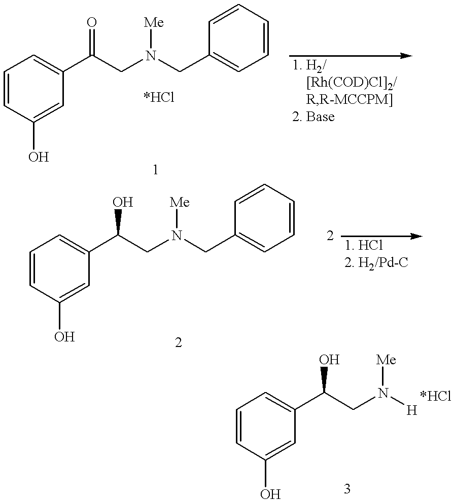
Preparation of the Catalyst Solution
4.3 g of dichloro-bis-[(cycloocta- 1,5-diene)rhodium (I)] and 9.4 g of RR-MCCPM (2R,4R)-4-(dicyclohexyl-phosphino)-2-(diphenylphosphino-methyl)-N-methyl-aminocarbonylpyrrolidine are added to 2 liters of degassed methanol under protective gas and stirred for 30 min. at ambient temperature.
Asymmetric hydrogenation of N-benzyl-N-methyl-2-amino-m-hydroxyacetophenone hydrochloride 1 to form N-benzyl-L-phenylephrine 2:
80 kg of N-benzyl-N-methyl-2-amino-m-hydroxyacetophenone hydrochloride 1, 0.58 kg of triethylamine and 240 l of methanol are placed in a 500 l autoclave, degassed and combined with the above catalyst solution. Then the mixture is heated to 50-55.degree. C. and a pressure of 20 bar is produced using hydrogen. After about 4 h total hydrogenation has taken place.
Further reaction of N-benzyl-L-phenylephrine 2 to form L-phenylephrine hydrochloride 3
Method A
The abovementioned hydrogenation solution is combined, in a second 500 l stirred vessel, ...
PUM
| Property | Measurement | Unit |
|---|---|---|
| temperature | aaaaa | aaaaa |
| temperature | aaaaa | aaaaa |
| temperature | aaaaa | aaaaa |
Abstract
Description
Claims
Application Information