Power system control apparatus and power system control method

a power system and control apparatus technology, applied in the direction of ac network voltage adjustment, instruments, ac network circuit arrangements, etc., can solve the problems of inability to increase the control precision of the apparatus, the amount of information included in the information is too large to be processed, and the voltage of the first and second substation adjacent to each other becomes unstabl

Inactive Publication Date: 2001-02-13
MITSUBISHI ELECTRIC CORP +1
View PDF6 Cites 54 Cited by
  • Summary
  • Abstract
  • Description
  • Claims
  • Application Information

AI Technical Summary

Problems solved by technology

However, in cases where the first substation is connected with a second substation, because a voltage fluctuation of the second substation adjacent to the first substation is not considered, there is a drawback that voltages of the first and second substations adjacent to each other become un...

Method used


Image

  • Power system control apparatus and power system control method
  • Power system control apparatus and power system control method
  • Power system control apparatus and power system control method

Examples


first embodiment

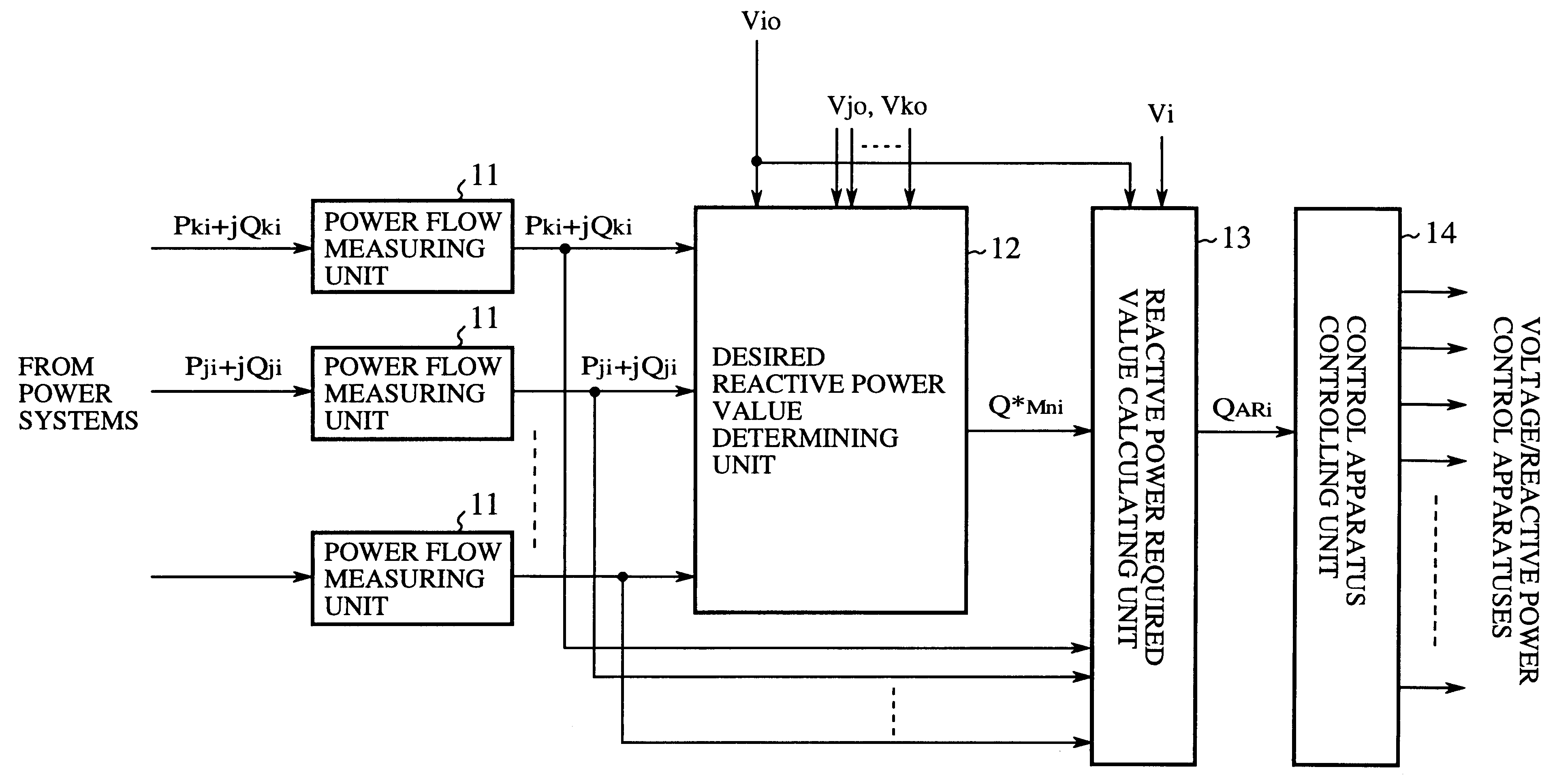
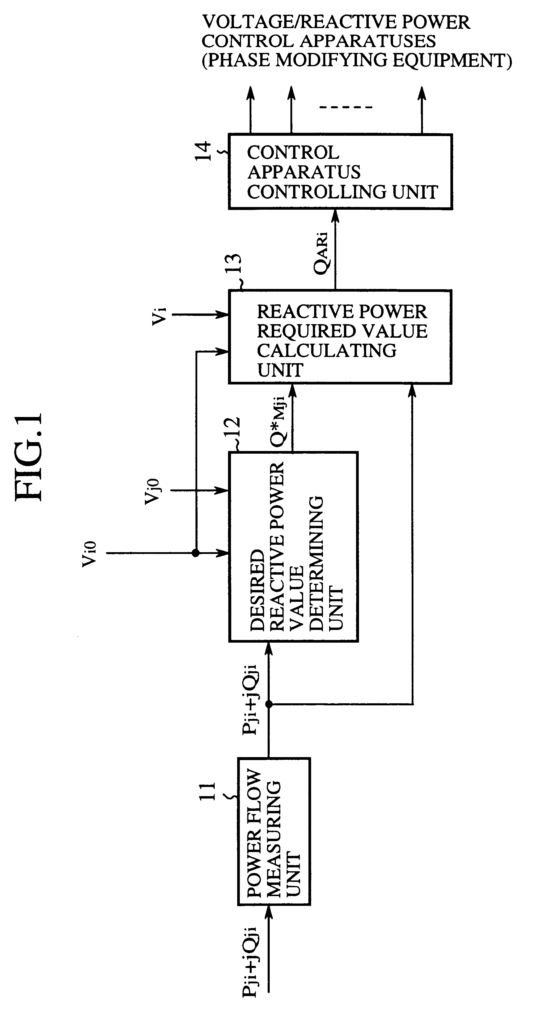
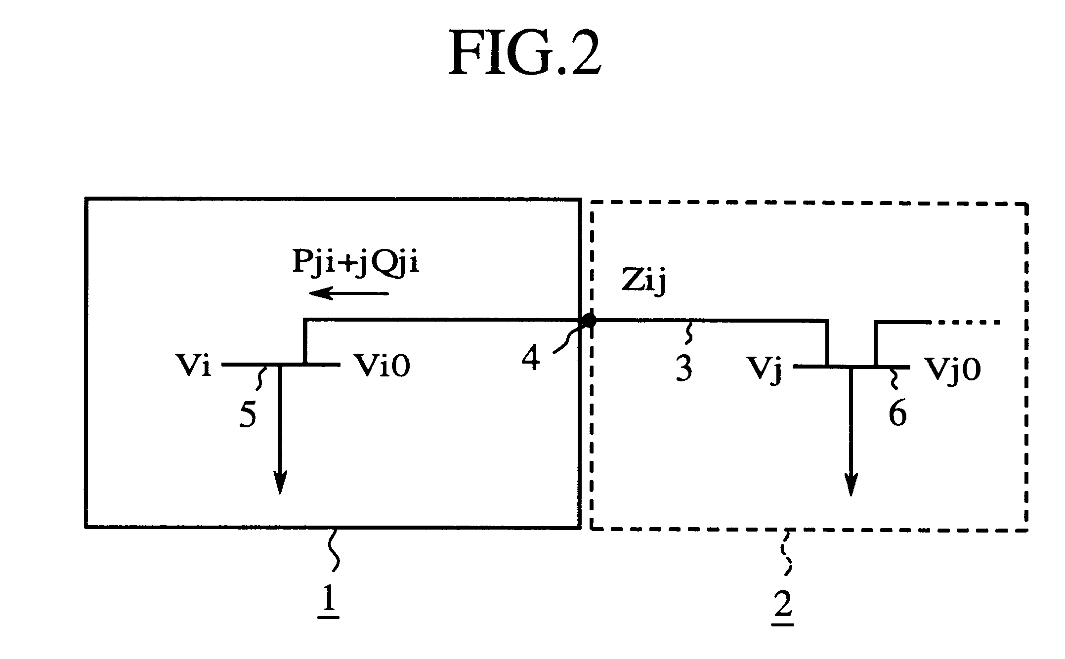
FIG. 1 is a block diagram of a power system control apparatus according to the present invention, and FIG. 2 is a diagram showing a power system to be controlled by the power system control apparatus shown in FIG. 1 and an adjoining power system adjacent to the power system to be controlled.

As shown in FIG. 2, a power system 1 to be controlled (hereinafter, called a to-be-controlled power system) is adjacent to an adjoining power system 2 through a boundary point 4. The adjoining power system 2 comprises a voltage monitoring bus 6 at which a voltage value V.sub.j is measured and a desired voltage value is V.sub.j0. The to-be-controlled power system 1 comprises a voltage monitoring bus 5 at which a voltage value V.sub.i is measured and a desired voltage value is V.sub.i0. The boundary point 4 is placed at a mid position of an interconnection line 3 connecting the to-be-controlled power system 1 and the adjoining power system 2, and an effective power flow P.sub.ji and a reactive powe...

embodiment 2

FIG. 11 is a block diagram of a power system control apparatus according to a second embodiment of the present invention, and FIG. 12 is a diagram showing two partial power systems composing a to-be-controlled power system by the power system control apparatus shown in FIG. 11 and two adjoining power systems adjacent to the to-be-controlled power system.

As shown in FIG. 12, a to-be-controlled power system 1 comprises a first partial power system la and a second partial power system 1b connected with each other through an interconnection line 3c. The first partial power system 1a is adjacent to a first adjoining power system 2a through an interconnection line 3a, and the second partial power system 1b is adjacent to a second adjoining power system 2b through an interconnection line 3b.

As shown in FIG. 11, a power system control apparatus comprises:

a first power flow measuring unit 11a, functioning as a flow measuring means, for measuring an effective power flow P.sub.ki and a reactiv...

embodiment 3

FIG. 16 is a block diagram of a power system control apparatus according to a third embodiment of the present invention. The description of composing elements indicated by reference numerals, which are the same as those used in FIG. 1, is omitted because the composing elements of FIG. 16 are the same as or equivalent to those of FIG. 1 indicated by the same reference numerals.

As shown in FIG. 16, a power system control apparatus comprises:

the power flow measuring units 11 respectively corresponding to one interconnection line 3; the desired reactive power value determining unit 12;

a system configuration supervising unit 31, functioning as a constant value changing means, for supervising a system configuration of power systems currently operated to detect the changing of the system configuration;

a control constant changing unit 32, functioning as the constant value changing means, for changing a value of the control constant K to a new value matching with a new system configuration i...


PUM


Abstract

A desired value of reactive power flow between a to-be-controlled power system and an adjoining power system is determined according to measured values of the reactive power flow and an effective power flow and desired voltage values of the to-be-controlled power system and of the adjoining power system. Thereafter, a required value of a reactive power of the to-be-controlled power system is calculated according to the desired value of the reactive power flow, the measured values of the reactive power flow and the effective power flow, and the desired voltage value and a measured voltage value in the to-be-controlled power system. Thereafter, a control apparatus having an electric capacity near to the required value of the reactive power is selected from control apparatus arranged in the to-be-controlled power system to make the selected control apparatus adjust a voltage of the to-be-controlled power system. Therefore, cooperation of the to-be-controlled power system with the adjoining power system can be performed by collecting locally-existing-information, and a voltage fluctuation and/or a reactive power fluctuation in the to-be-controlled power system can be immediately suppressed.

Description

1. Field of the InventionThe present invention relates to a power system control apparatus and a power system control method in which voltage and reactive power in a power system are adjusted to desired values by operating a control apparatus of the power system.2. Description of Related ArtAs is disclosed in pages 1200-1201 of lectures of a National Conference of Japanese Electrotechnical Committee held in 1987, in a conventional power system control method, a voltage of a first substation corresponding to one power system and a reactive power flow transmitted through a bank are measured, and phase modifying equipment (for example, a transformer tap, a condenser, a reactor and the like) arranged in the first substation is controlled according to measured values.Accordingly, in cases where the first substation is isolated from another substation, a voltage fluctuation in the first substation can be suppressed according to the conventional power system control method by controlling t...

Claims


Application Information

Patent Timeline
IPC IPC(8): H02J3/18G05F1/70H02J3/16
CPCH02J3/1835H02J3/1871Y02E40/30
Inventor TANIMOTO, MASAHIKOIZUI, YOSHIOKOWADA, YASUYUKIIBA, KENJIFUKUTA, NAOTODENO, KENICHISASAKI, TETSUO
Owner MITSUBISHI ELECTRIC CORP
Why Eureka
Try Eureka