Radio-frequency radiation source, radio frequency radiation source array, antenna module, and radio equipment

a radio frequency radiation source and array technology, applied in the field of radio frequency radiation sources, radio frequency radiation source arrays, antenna modules, etc., can solve the problems of reduced antenna gain and efficiency, increased antenna noise, and complicated circuit construction

Inactive Publication Date: 2001-02-13
MURATA MFG CO LTD
View PDF5 Cites 39 Cited by
  • Summary
  • Abstract
  • Description
  • Claims
  • Application Information

AI Technical Summary

Problems solved by technology

In such a system, because the loss in the switch(diode) is great, there is a problem in that the antenna gain and efficiency are reduced and the antenna noise is increased.
Further, because the radiation source and the switch are constructed using different circuits, there is a problem in that the circuits'construction becomes complicated.
Therefore, at least two diodes are required, and a circuit (DC biasing circuit) applying controlling voltages to these diodes becomes complicated. FIG. 16 shows an example.

Method used


Image

  • Radio-frequency radiation source, radio frequency radiation source array, antenna module, and radio equipment
  • Radio-frequency radiation source, radio frequency radiation source array, antenna module, and radio equipment
  • Radio-frequency radiation source, radio frequency radiation source array, antenna module, and radio equipment

Examples


Embodiment Construction

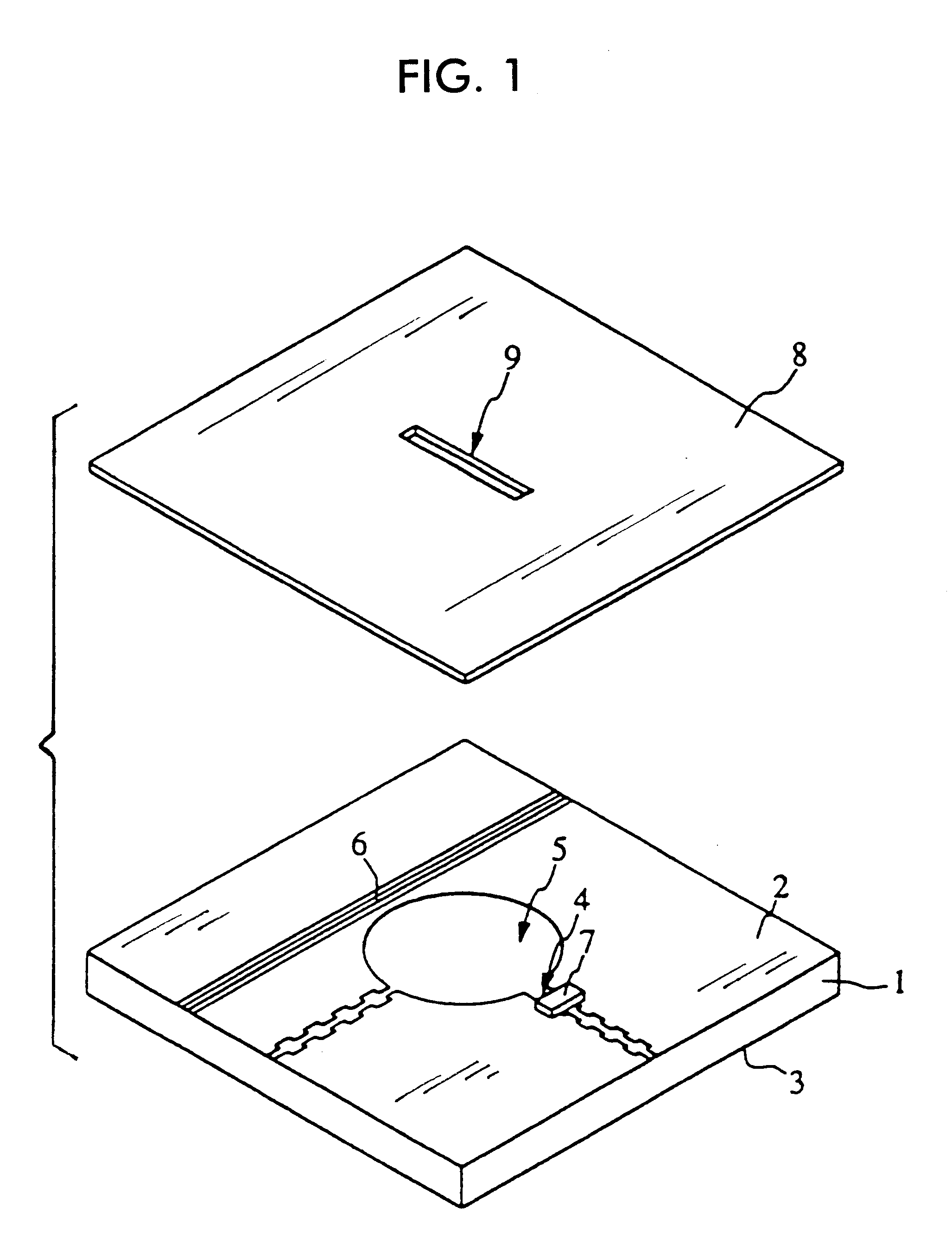
The construction of a radio-frequency radiation source according to a first embodiment is explained with reference to FIGS. 1 through 4.

FIG. 1 is a perspective view of a radio-frequency radiation source. Here, reference numeral 1 represents a dielectric plate and on the upper and lower surfaces in the figure electrodes 2 and 3 are formed. In these electrodes 2 and 3, electrodeless parts are formed at opposing locations to sandwich the dielectric plate 1. The electrodeless parts are in a radial form, but they can be appropriately modified in accordance with their purposes. In the present embodiment circular electrodeless parts are preferable in order to realize a high Q. Further, although the external shape of opposing electrodeless parts are desirable to be nearly in agreement, they may not be. Reference numeral 5 represents an electrodeless part on the upper surface in the figure. In a section of the upper surface 5 a slit having a fixed width and fixed length is formed and a switc...


PUM


Abstract

A radio-frequency radiation source comprises electrodes containing opposing electrodeless parts formed on both sides of a dielectric plate in which the electrodeless parts are made to function as a dielectric resonator, a slit formed in the electrodeless part, and a switching element mounted over the slit. Further, a transmission line coupled to the dielectric resonator is provided. As constructed this way, the resonance frequency of the resonator is switched by turn-on and turn-off of the switching element. When the resonator resonates with the frequency of a signal propagated through the transmission line, the energy of the electromagnetic field is radiated to the outside through a slot.

Description

1. Field of the InventionThe present invention relates to a radio-frequency radiation source, radio-frequency radiation source array, antenna module, and radio equipment to be used in radio-frequency bands of a millimeter wave region, and so on.2. Description of the Related ArtIn a radio-frequency antenna, when a circuit to turn on and off an electromagnetic wave to be output from the radiation source is constructed, heretofore a switch is provided between an element or a conductor pattern to be used as a radiation source and a feed system. The example is shown in FIG. 15. FIG. 15A is an equivalent circuit diagram and FIG. 15B is a perspective view showing the construction of a radio-frequency circuit portion. In this way, a diode D1 is provided in series to a feed circuit of a square patch antenna, and a series circuit of a diode D2 and a resistor R is provided between the feed circuit and ground.The above circuit constitutes a so-called SPST (Single Pole Single Throw) radio-freque...

Claims


Application Information

Patent Timeline
Patent Type & Authority Patents(United States)
IPC IPC(8): H01P7/10H01Q15/08H01Q3/24H01Q13/10H01Q21/08H01Q23/00
CPCH01P7/10
Inventor KATO, TAKATOSHISAKAMOTO, KOICHIIIO, KENICHIISHIKAWA, YOHEI
Owner MURATA MFG CO LTD
Why Eureka
Try Eureka