Directivity control antenna apparatus for shaping the radiation pattern of antenna of base station in mobile communication system in accordance with estimated directions or positions of mobile stations with which communication is in progress

a technology of directivity control and antenna apparatus, which is applied in direction finders, differential interacting antenna combinations, instruments, etc., can solve the problems of limited channel frequency and frequency bandwidth, communication is only possible, and the number of channel frequencies and frequency bandwidths is limited, so as to achieve the maximum number of mobile stations which can be accommodated by a mobile communication system

Inactive Publication Date: 2001-02-13
PANASONIC CORP
View PDF20 Cites 107 Cited by
  • Summary
  • Abstract
  • Description
  • Claims
  • Application Information

AI Technical Summary

Benefits of technology

To achieve the above objective, the present invention provides a mobile communication system whereby each base station includes incoming direction estimation means for estimating the incoming direction of radio waves which are received from a mobile station, to thereby estimate the direction of the mobile station with respect to the antenna of the base station. Based on the results of such estimation, the radiation pattern of the antenna of the base station is formed with a directivity peak which is oriented in the direction of that mobile station by antenna directivity control means. To achieve this, the antenna directivity control means appropriately controls the phase and amplitude of respective transmission / received signals that are supplied to / received from the array elements constituting the array antenna.
Furthermore, if estimated positions of respective mobile stations are derived by the apparatus, then it may be possible to form a single peak which is shaped such as to enable communication with each of a plurality of mobile stations that are located sufficiently adjacent to one another, while mininizing the danger of interference with communication between other base stations and mobile stations of the system.

Problems solved by technology

With such a prior art system, in general communication is only possible between a base station and those mobile stations which are located within the service area of the base station, i.e. an area of nominally predetermined size.
When such prior art technology is used, the number of mobile stations which can be accommodated by the service area of a single base station is limited to the total number of communication slots that are allocated to the mobile stations, in the case of time division multiplexing, while that number of mobile stations is limited to the total number of frequency channels, in the case of frequency division multiplexing, and is limited by the degree of effectiveness of interference prevention (which is determined by the ratio of the data transfer rate to the spectrum dispersion chip rate) in the case of code division multiplexing.
There are limitations on frequency resources, so that there are limitations on the number of channel frequencies and frequency bandwidth which can be allocated to mobile communication systems, and this places an upper limit on the number of mobile stations which can be accommodated by a mobile communication system.
In the prior art, in such a case, i.e. in which there is communication channel capacity available in the overall system, it may not be possible to achieve communication in some instances due to lack of communication channel capacity in one or more base stations.

Method used


Image

  • Directivity control antenna apparatus for shaping the radiation pattern of antenna of base station in mobile communication system in accordance with estimated directions or positions of mobile stations with which communication is in progress
  • Directivity control antenna apparatus for shaping the radiation pattern of antenna of base station in mobile communication system in accordance with estimated directions or positions of mobile stations with which communication is in progress
  • Directivity control antenna apparatus for shaping the radiation pattern of antenna of base station in mobile communication system in accordance with estimated directions or positions of mobile stations with which communication is in progress

Examples


first embodiment

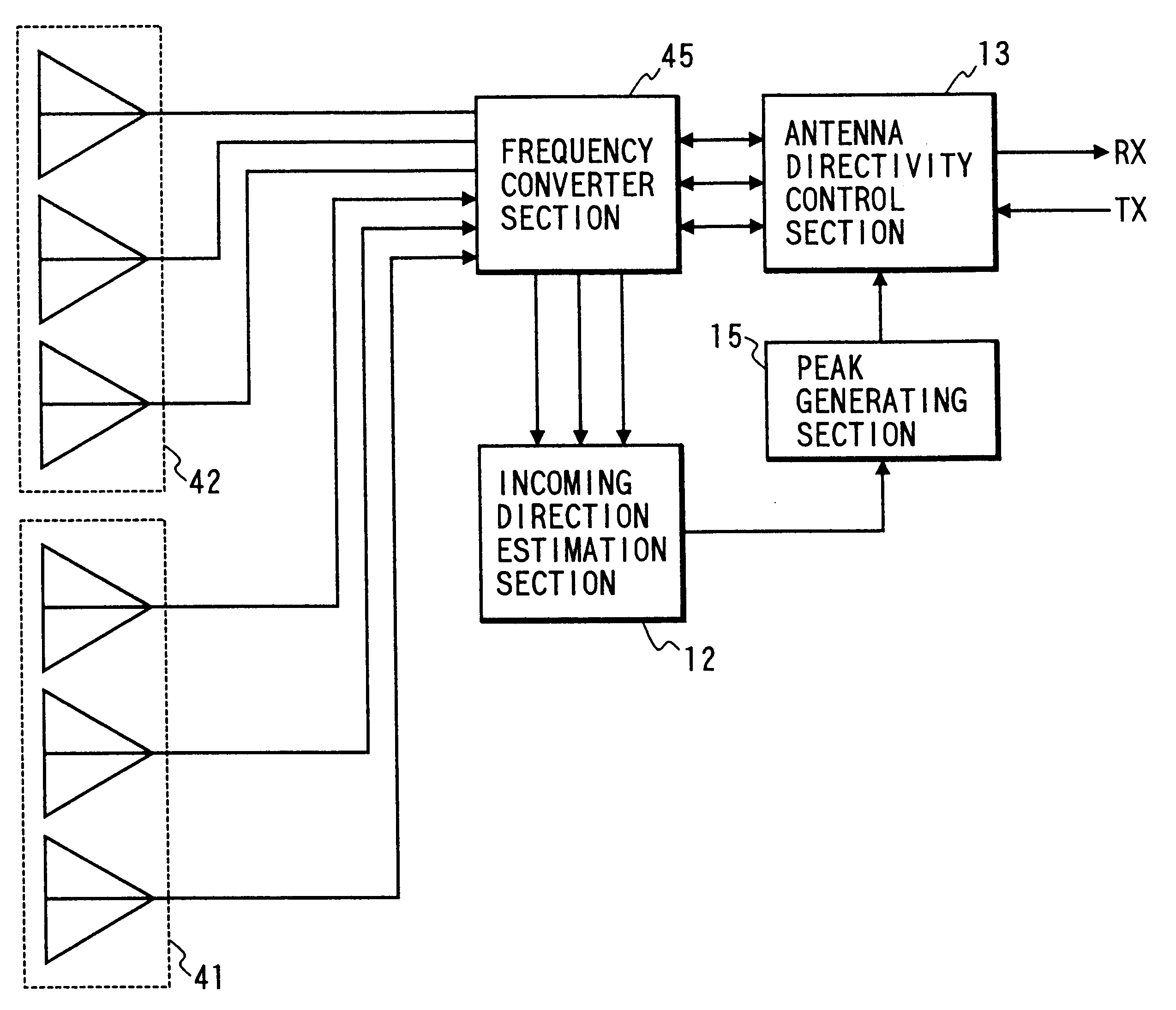
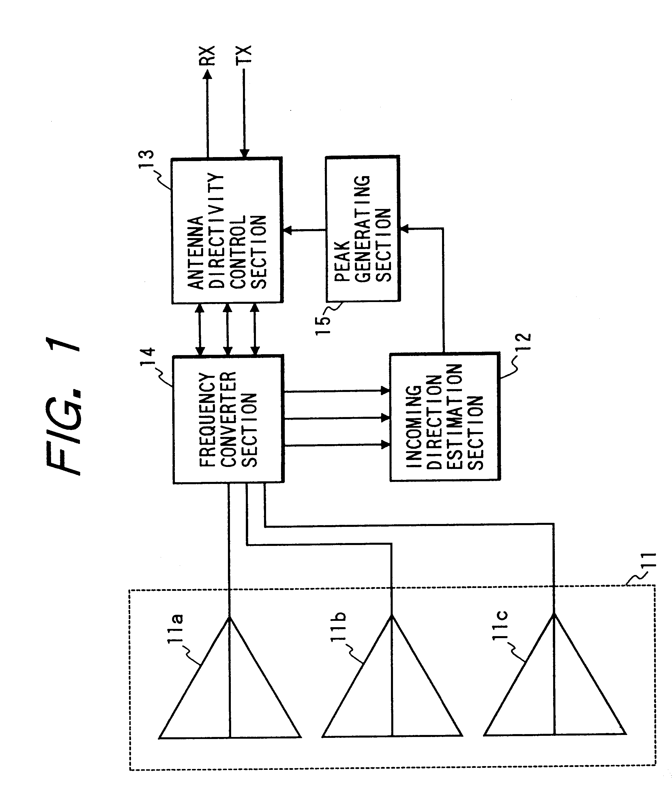
Embodiments of the present invention will be described in the following, referring to the drawings. FIG. 1 is a system block diagram of a directivity control antenna apparatus according to the present invention. In FIG. 1, 11 is an array antenna of a base station of a mobile communication system. The array antenna 11 is formed of a plurality of antenna elements, designated here as 11a, 11b, 11c, and can be for example a microstrip antenna, or an array of spaced dipole antennas having rear reflector elements. 12 is an incoming direction estimation section which operates on received signals obtained by the elements of the array antenna 11, to estimate the respective incoming directions of radio waves transmitted from mobile stations. 15 is a peak generating section, which operates on direction data supplied by the incoming direction estimation section 12, to generate control signals for controlling an antenna directivity control section 13 such as to produce peaks in the directivity o...

third embodiment

As described hereinabove, it is only possible for the incoming direction estimation section to obtain accurate direction information for each of the mobile stations from which radio waves are received, and an accurate estimate of the total number of these mobile stations, if that number of mobile stations is no greater than the total number of elements of the array antenna whose signals are used for direction estimation. FIG. 19 is a system block diagram of the invention which enables that limitation to be overcome. In FIG. 19, 51 is a first array antenna, which is normally used to obtain received signals for incoming direction estimation purposes, and 52 is a second array antenna, which is normally utilized as a data transmitting and receiving antenna. 53 is an incoming direction estimation section, 54 is an antenna directivity control section, 55 is a frequency conversion section, 56 is a received signal strength judgement section, and 57 is a peak generating section.

The operation...

fourth embodiment

Before describing the present invention, some basic principles of a linear array antenna which is an essential feature of that embodiment will be summarized, referring first to FIG. 23. This illustrates the relationship between radio waves Sm(t) which are incident on a linear array antenna having elements E that are arrayed with a spacing d. The incoming direction of the radio waves is expressed here by the angle em between that direction and a normal to the array direction of the antenna. As illustrated, there will be a phase difference between the signals obtained from adjacent elements of the antenna, due to the path difference d.sin .THETA.m between the distance travelled by a wave front in reaching these elements. However when the incoming direction of radio waves is estimated for such an antenna, e.g. by using the MUSIC method, and if the antenna can receive radio waves from directions extending in 360.degree. about its array axis, then the angle which is thereby estimated rep...


PUM


Abstract

In a mobile communication system, each base station is provided with an array antenna, a section for estimating the respective directions of one or more mobile stations with which the base station is in communication, based on estimated incoming directions of radio waves received from these mobile stations, and sections for operating on respective signals of the antenna elements constituting the array antenna such as to shape the radiation pattern of the antenna to form peaks of directivity which are oriented in the estimated directions of these mobile stations, and can include a capability for shaping these peaks in accordance with estimated positions of these mobile stations, thereby minimizing interference between transmissions from that base station and communication being executed between other adjacent stations of the system, and minimizing the number of different transmission frequencies required in the overall system.

Description

1. Field of ApplicationThe present invention relates to a directivity control antenna apparatus for use in base stations and mobile stations of a mobile communication system such as a radio paging system, cellular telephone system, etc.2. Prior ArtIn the prior art, methods such as time division multiplexing (TDMA), frequency division multiplexing (FDMA), code division multiplexing (CDMA), etc., have been used in the field of mobile communication, as methods for communicating with a plurality of mobile stations within areas which have been allocated to respective base stations of a mobile communication system. With time division multiplexing, a channel having a single frequency is divided into equidistant intervals along the time axis to provide communication slots, for enabling communication between a plurality of mobile stations and a base station, while with frequency division multiplexing this is accumplished by using a plurality of different frequency channels, Alternatively, wi...

Claims


Application Information

Patent Timeline
Patent Type & Authority Patents(United States)
IPC IPC(8): H01Q3/30H01Q3/26H01Q21/29H01Q21/00H01Q21/08H04Q7/36G01S3/14G01S3/46H04Q7/38H04B7/10H04B7/26H04W16/28
CPCH01Q3/2605H01Q3/30H01Q21/08H01Q21/29H04W16/28G01S3/46
Inventor FUKAGAWA, TAKASHIHASEGAWA, MAKOTOMATSUOKA, AKIHIKOADACHI, NAOKI
Owner PANASONIC CORP
Why Eureka
Try Eureka