Injection anchor

a technology of injection or grouting and anchors, which is applied in the direction of engine lubrication, foundation repair, etc., can solve the problems of significant production problems, inability to mass production, and inconvenient assembly of prior art injection or grouting anchors. , to achieve the effect of convenient assembly

Inactive Publication Date: 2001-02-20
INT INTEC PATENT HLDG ESTAB
View PDF3 Cites 16 Cited by
  • Summary
  • Abstract
  • Description
  • Claims
  • Application Information

AI Technical Summary

Benefits of technology

The object of the invention is the creation of an injection or grouting body that can be adapted on site to local requirements and be easily assembled, installed and immediately employed at the construction site. It is proposed that this object be addressed by an injection or grouting body of the type first described, wherein the filling tube is designed as a tube of fabric or similar material and wherein arranged axis-parallel between the fabric stockings are at least two reinforcing wires and / or rods and / or pipes / and / or ridged sheet metal strips.
Both the length of the grouting body and the adaptation to the desired stress or load dispersal can be easily determined on site, for example through the selection of the number and cross sections of the reinforcing elements to be employed.
In a further embodiment of the invention, the fabric stockings are embodied at least in sections as a metal fabric mesh, an arrangement that broadens considerably the range of applicability. The mesh fabric embodiments of this arrangement is, for example, designed of very fine wires or metal fibres which, owing to their looped arrangement, can expand up to about 20% of the circumference of the stocking.
In a further variant of the invention, the wires and / or rods are designed in a U-shape, or other comparably acting contour, whereby their bent positions are preferably arranged at one end of the injection or grouting body. The reinforcing elements of the injection or grouting body are disposed in its peripheral region. Further advantages of this variant are realized because of the significantly increased resistance afforded by such a wire or rod bundle against being pulled out.
If, for example, load or moment dispersal is required in certain serially-disposed regions of varying sizes, wires, pipes or rods, whose thickness and number can be selected in accordance with load or moment dispersal requirements, can be selected for each region, in which case a bundle of wires or rods is assembled for the purpose of dispersing load from a single region, while a further bundle of wires, pipes or rods takes over load or moment dispersal from another region. An advantage of this approach is that the tensile strength of a wire, pipe or rod bundle can be designed to meet the requirements and be exploited; in such a case, further loads do not generally act on this wire or rod bundle. In such an arrangement, even the individual load regions are not generally influenced by one another and a single injection body can thus displace or transfer loads or moments from various regions relatively independently of other regions.
This arrangement, by permitting transmission of vibrational energy to all regions of the injection anchor may further improve the flow capability of the filler. This arrangement permits the injection bodies to be produced in long lengths, without hampering filler injection. This procedure permits the production of anchors in lengths of 50 m or longer. This is one advantage resulting from the fact that this type of injection body can be produced on-site.

Problems solved by technology

If, for example, excessive loads or moments have to be dispersed in certain regions over predetermined lengths or borehole depths, the prior art injection or grouting anchors are not suitable or not particularly suitable.
The prior art injection or grouting anchors are factory manufactured, which means that the borehole depths, which are selected to ensure special stress or load dispersal, must be known at the time the anchor is being manufactured, which entails significant production problems, since the anchors have to be made to order.
Mass production is not possible in this case.

Method used


Image

  • Injection anchor
  • Injection anchor
  • Injection anchor

Examples


Embodiment Construction

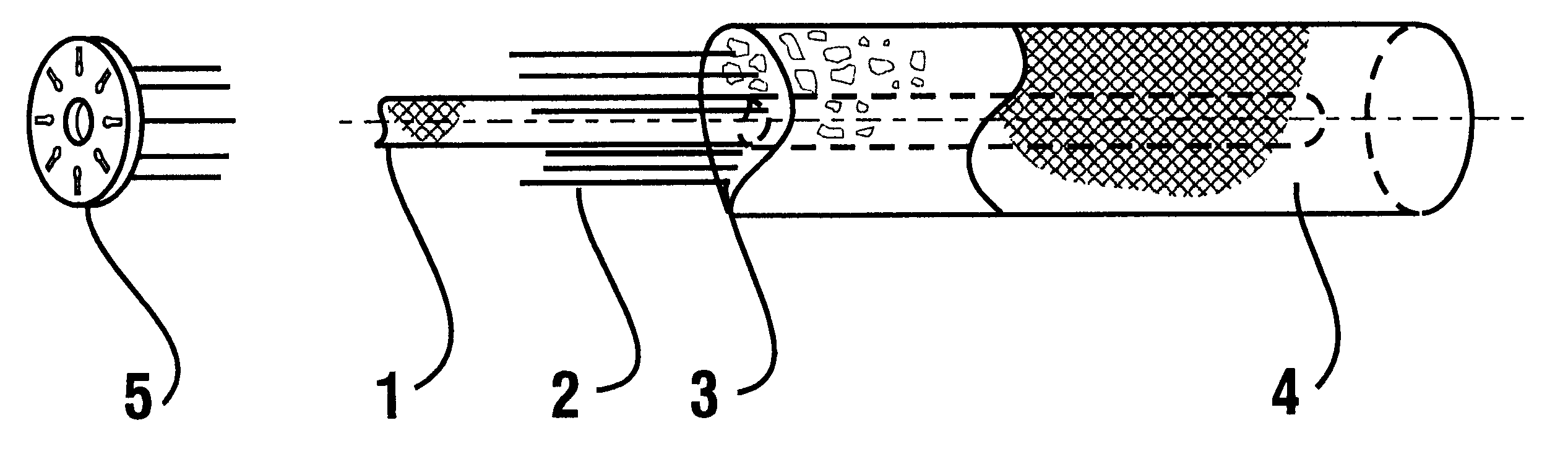
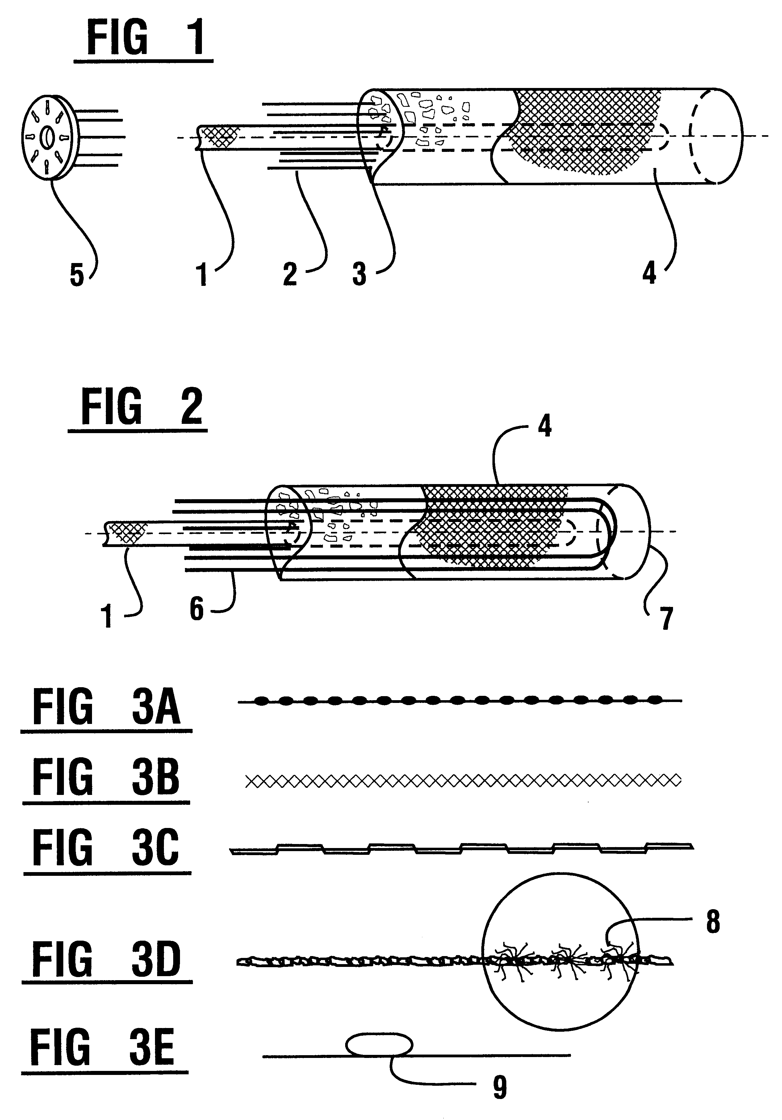
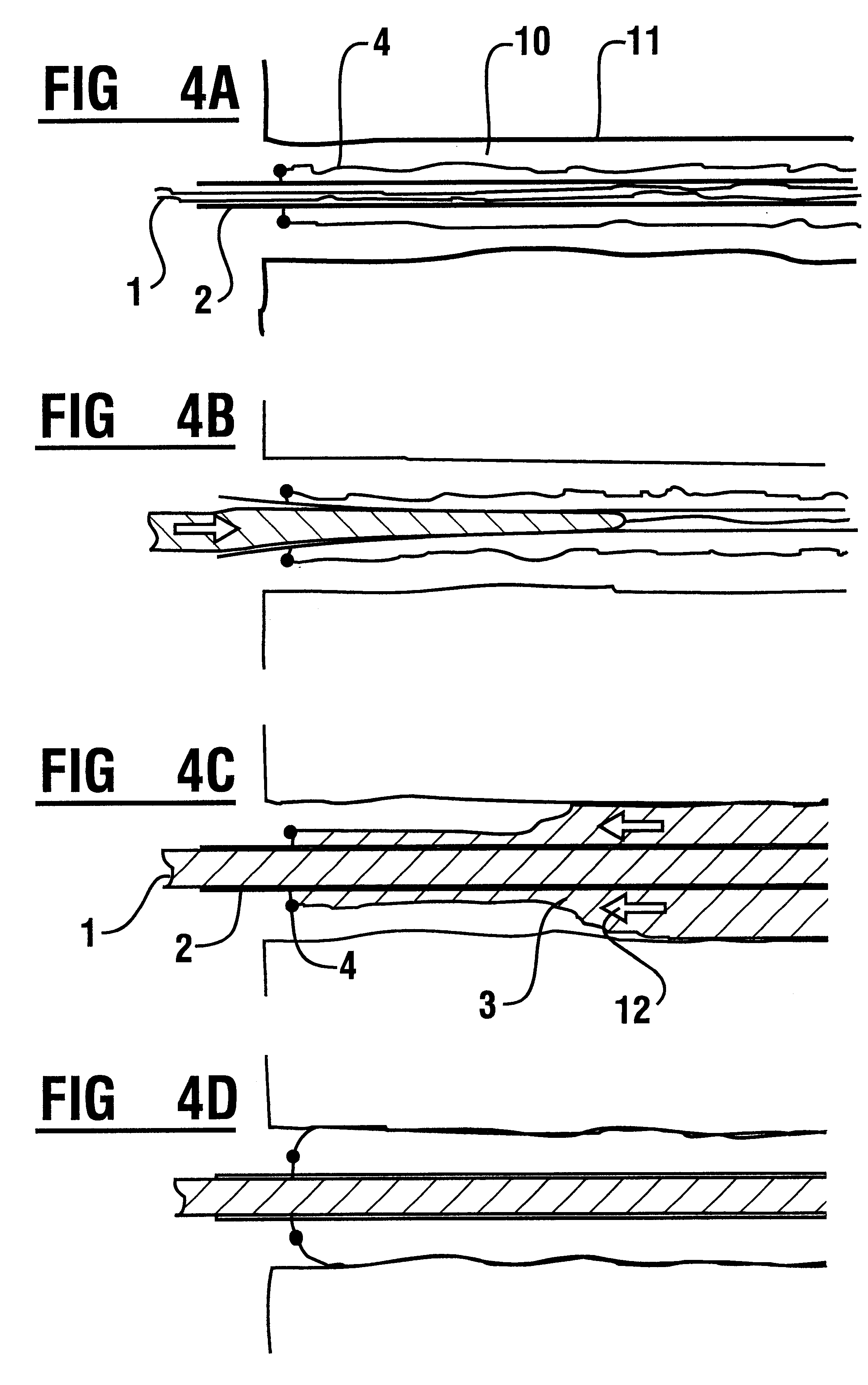
FIG. 1 shows in perspective an exploded view of an injection body as proposed in the filled state. The inner deformable structure which in the embodiment shown comprises fabric tube 1 is surrounded by reinforcing elements 2, which can comprise rods, wires, pipes or ridged sheet metal or other suitable elements. Reinforcing elements 2 in the present embodiment example comprise rods or bars, each of which is slightly shorter than the integral length of the injection body or can comprise partial pieces that are not indicated in greater detail. The length and cross section of the reinforcing elements 2 are determined at the construction site on the basis of the data available. Next, the assembled injection body is also installed. An additional fabric tube 4 or similar structure, which is closed at the foot-end of the injection body, surrounds the entire body. The inner fabric tube is correspondingly shorter, so that mortar 3 which has been introduced via the inner fabric tube, exits the...


PUM


Abstract

An injection or grouting body for the transfer of mechanical stresses in structures in above-ground or below-ground construction, and for insertion into a borehole, in slits or similar openings, has a centrally-arranged filling tube and at least one fabric stocking surrounding the filling tube. The filling tube is embodied as a fabric stocking and one or a plurality of reinforcing wires and / or rods, and / or pipes and / or ridged sheet metal strips are arranged on site so as to be adaptable, axis-parallel between the fabric stockings. An outer closed fabric stocking is arranged along the axis of the injection body about its inner filling tube (Fabric tube) that is open at its lower end. The reinforcing wires or rods are arranged on the outside of the inner fabric stocking and are attached to the fabric of the outer stocking in such a way that it can be ensured that, following filling or grouting, the reinforcement will remain in position.

Description

This invention relates to anchoring devices, more specifically, the invention relates to an injection or grouting body which, comprising a centrally-arranged filling tube and at least one fabric stocking surrounding the filling tube, is inserted into a borehole, into slits or similar openings in order to transfer mechanical stresses in structures in above- and under-ground construction.So-called injection or grouting anchors are used to secure construction components to unstable backgrounds, strengthen structures on construction sites and render safe buildings that have been threatened by damage caused by mining. As disclosed in DIN 4125, used in such cases are construction elements in respect of which a grouting body, having been created by the forcing of grout around the rear part of a steel stress member installed in the ground, is attached via steel stress members and anchor head to the construction component or mine component to be anchored.Another important application is the ...

Claims


Application Information

Patent Timeline
Patent Type & Authority Patents(United States)
IPC IPC(8): F01M11/00F01M11/03E21D20/00E21D20/02E21D21/00E02D5/54E02D5/80E02D37/00
CPCE02D5/80E21D20/021E21D21/0026E02D5/54E02D37/00E02D2250/003E02D2300/0029E02D2300/0034E21D2021/006E21D2021/0073F16H57/0404E21D21/006E21D21/0073
Inventor SOBEK, PETER
Owner INT INTEC PATENT HLDG ESTAB
Why Eureka
Try Eureka