Suction flow preswirl control bypass structure for blowers

a technology of bypass structure and suction flow, which is applied in the direction of machines/engines, stators, liquid fuel engines, etc., can solve the problems of not providing a concrete structure for rationally controlling energy, and achieve the effects of reducing the shaft power of the fan, improving the efficiency of the fan, and increasing the pressure ris

Inactive Publication Date: 2001-02-20
SHOWA FURYOKU KIKAI
View PDF8 Cites 3 Cited by
  • Summary
  • Abstract
  • Description
  • Claims
  • Application Information

AI Technical Summary

Benefits of technology

Consequently, the energy based on the tangential velocity of the prerotation flow generating at `the region ahead of an impeller` inside the suction pipe of a fan can be rationally controlled, accordingly, the fan efficiency can be improved by the decrease of the shaft power of a fan and / or the increase of the pressure rise owing to a fan impeller. Besides, the fan noise can be reduced by the improvement of air flow at the portion in close vicinity to an impeller inside the suction pipe.
In the case that an air chamber is a box disposed outside a suction pipe and communicating passages are tubes connecting the box to the suction pipe they will be also installed on the fans already made. Not only the fan efficiency of the fan can be improved but the fan noise thereof can be reduced. Of course, also in the case that a cylindrical closed chamber formed on the periphery of `the region ahead of an impeller` of the suction pipe is used as an air chamber and the holes punched on the peripheral wall of a suction pipe, partitioning off the cylindrical closed chamber and the suction pipe, are adopted as communicating passages, the fan displaying the above-mentioned effect can be made compact.
Regulating the length from the specified reference point to the upstream point of a by-pass unit for controlling the prerotation of flow and the length from the above-mentioned reference point to the downstream point thereof as described in claim 4 promotes the effect of the present invention, and provides the useful indexes for designing a fan.

Problems solved by technology

According to such a prior theory the ideas mentioned above do not provide a concrete structure for rationally controlling the energy based on the tangential velocity of prerotation flow.

Method used


Image

  • Suction flow preswirl control bypass structure for blowers
  • Suction flow preswirl control bypass structure for blowers
  • Suction flow preswirl control bypass structure for blowers

Examples


Embodiment Construction

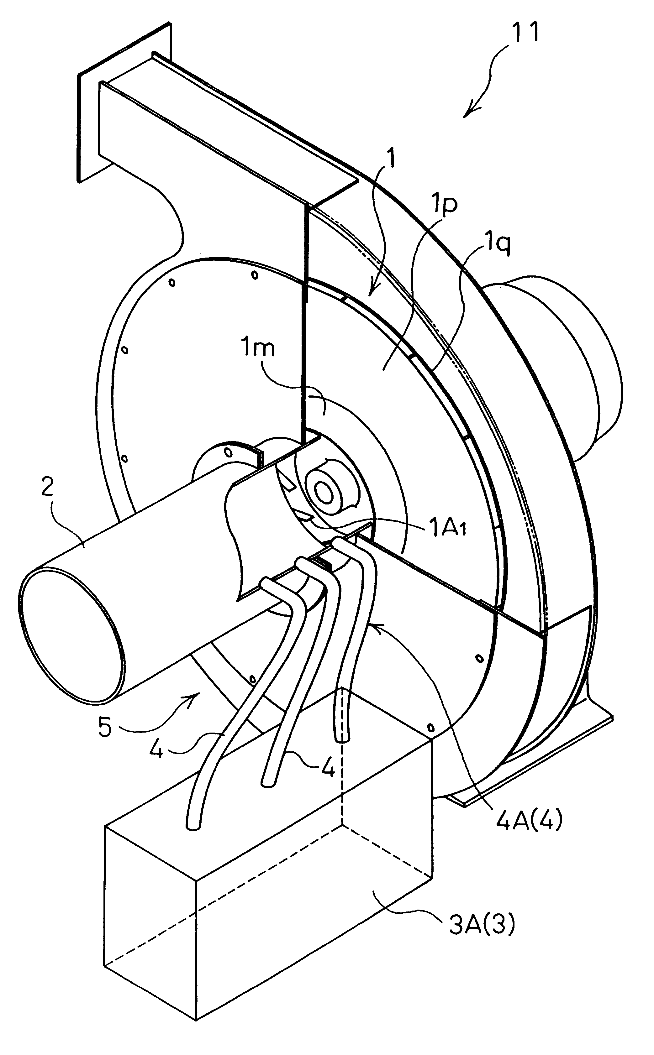
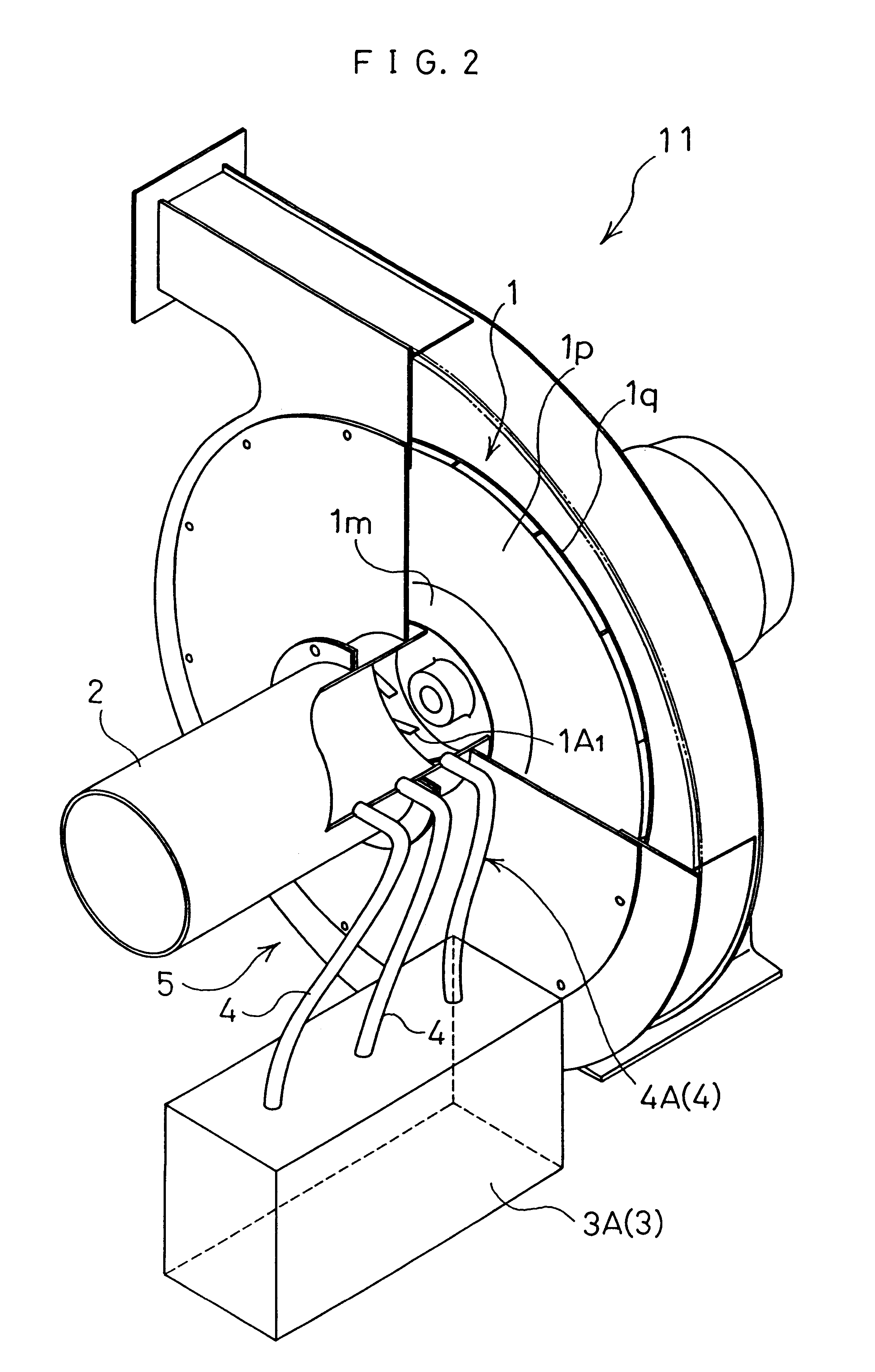
A by-pass unit for controlling the prerotation of flow in the suction pipe of a fan according to the present invention is disclosed by referring to some drawings indicating favorable embodiments of the invention. FIG. 2 shows a schematic drawing of a centrifugal flow fan 11, to which a by-pass unit for controlling the prerotation of suction air according to the invention is applied at `the region ahead of an impeller` of a suction pipe 2 for introducing suction air into an impeller 1.

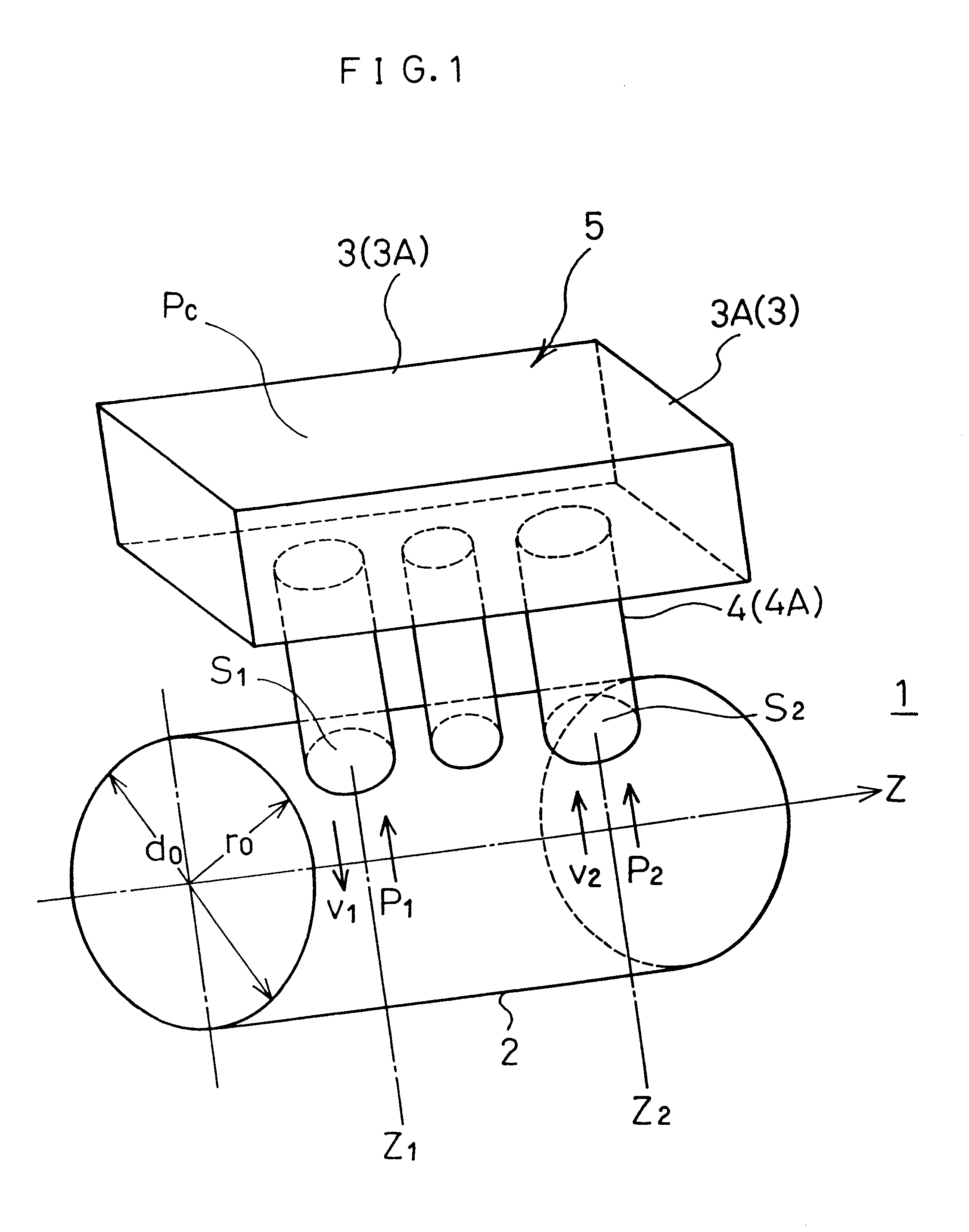
An air chamber 3 forming a closed spatial region is equipped outside `the region ahead of an impeller` of the suction pipe 2, which is connected with the suction pipe 2 by means of plural communicating passages 4 arranged along the flowing direction of suction air. At least three communicating passages are provided along the flowing direction of suction air as described later. In FIG. 2, the air chamber 3 forming a closed spatial region is a box 3A equipped outside the suction pipe 2. In this embodiment...


PUM


Abstract

The objects of the present invention are to improve the fan efficiency by the decrease of the shaft power of a fan and/or the increase of the pressure rise owing to a fan impeller, which are accomplished by the rational control of the energy based on the tangential velocity of the prerotation flow generating at "the region ahead of an impeller' inside the suction pipe of a fan, and to reduce fan noise by the improvement of air flow at the portion in close vicinity to an impeller inside the suction pipe. The present invention is related to a by-pass unit (5) disposed upstream an impeller to control the energy generated by the air flowing into the impeller (1), comprising a specific region of a suction pipe (2) as a part of the by-pass unit (5), an air chamber (3), through which the air is able to pass, forming a closed spatial region outside the suction pipe (2), and communicating passages (4) for connecting the closed spatial region to the suction pipe (2).

Description

The present invention relates to a by-pass unit for controlling the prerotation of flow in a suction pipe, in more particular, a unit for controlling the prerotation of the air flowing into an impeller of a fan, e.g., of the centrifugal flow type, the axial flow type and the mixed flow type, in order to increase fan efficiency and to reduce fan noise.PRIOR ARTVarious technical ideas have been made to suppress the prerotation of the air flowing into an impeller of a pump and / or a fan. For instance, `Designing and Drawing for Centrifugal Flow Pump` authored by Susumu TERADA, Jun. 15, 1972, 4th edition, (published by Riko Tosho Co. Ltd.,), page 36 and pages 66 to 71, `Centrifugal and Axial Flow Fan and Compressor` authored by Takebumi IKUI, Jul. 30, 1964, 5th edition, (published by Asakura Shoten Co. Ltd.,), pages 222 to 225, and `Turbo Fan and Compressor` authored by Takebumi IKUI and Masahiro INOUE, Aug. 25, 1988, (published by Corona Co. Ltd.,) teach that a flat or cylindrical baffl...

Claims


Application Information

Patent Timeline
Patent Type & Authority Patents(United States)
IPC IPC(8): F04D27/02F04D29/42F04D29/44F15D1/02
CPCF04D29/4213F04D27/009F04D29/66
Inventor HAYASHI, SHIROKURAMOTO, NAOTAKA
Owner SHOWA FURYOKU KIKAI
Why Eureka
Try Eureka