

Transmission conduit and method of installation
- Summary
- Abstract
- Description
- Claims
- Application Information
AI Technical Summary
Benefits of technology
Problems solved by technology
Method used
Image

Examples
example of application
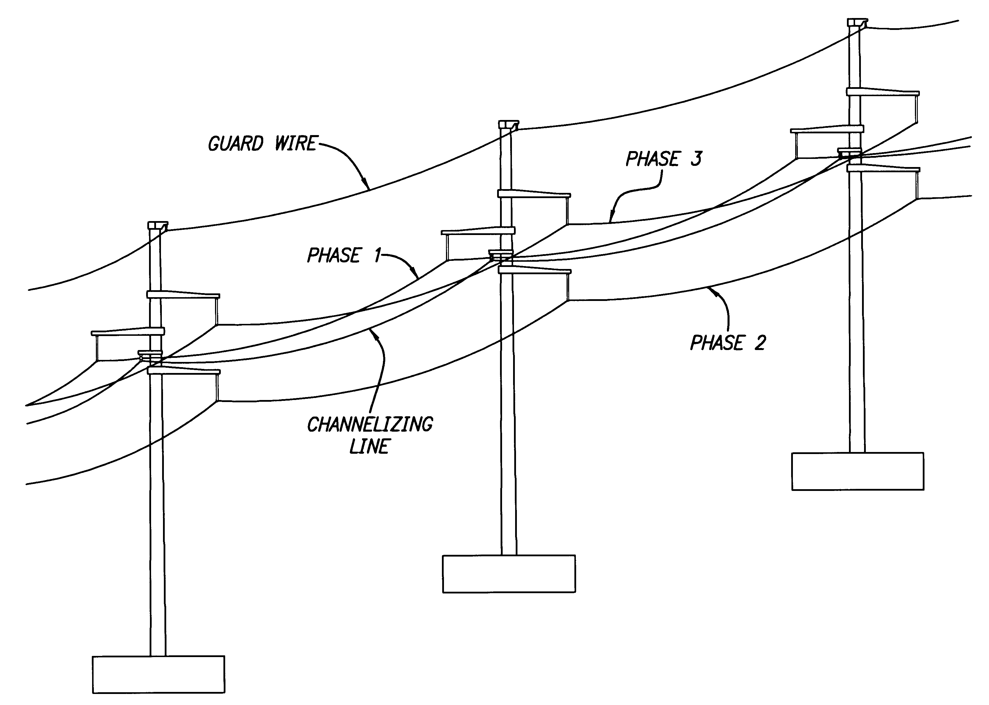
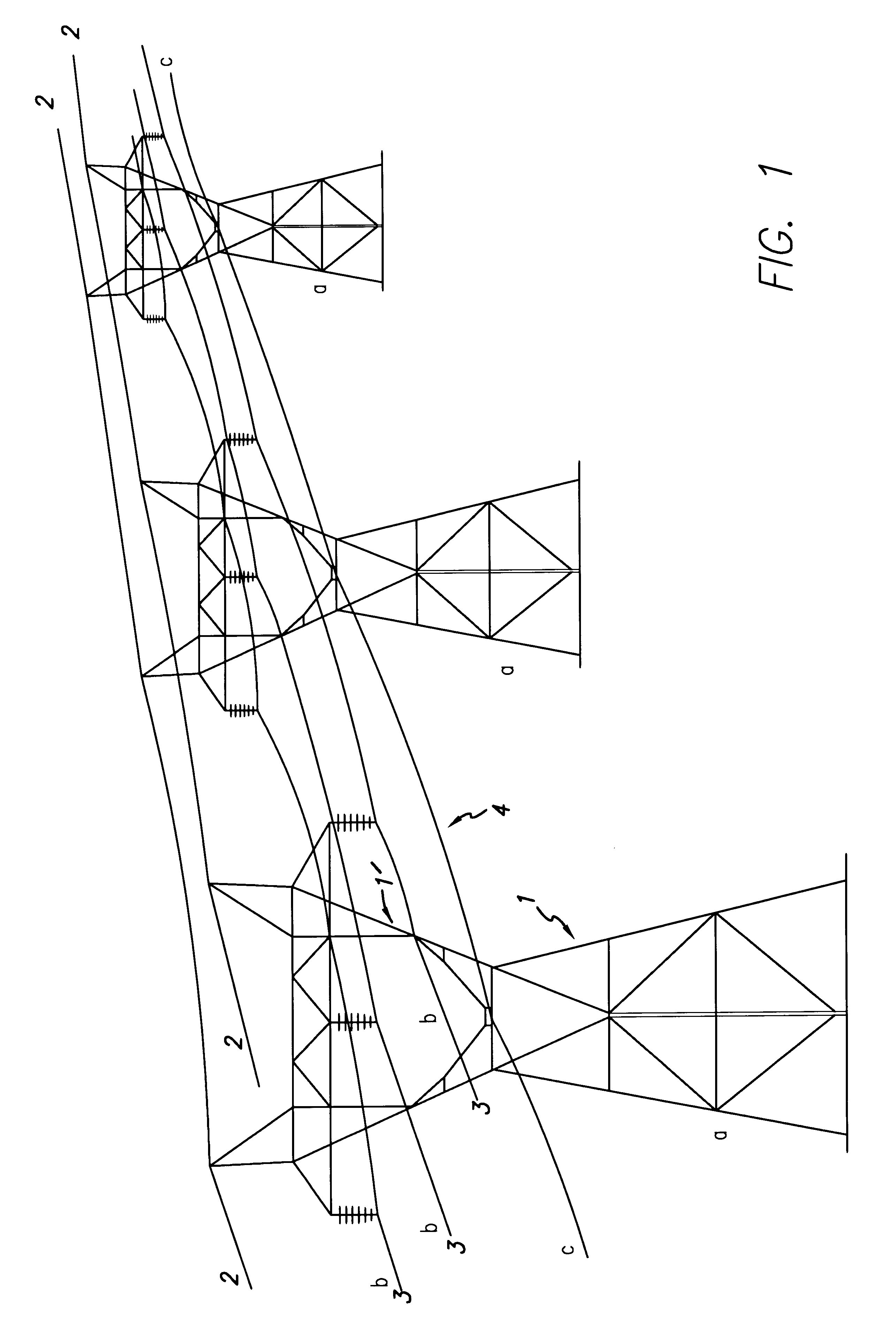
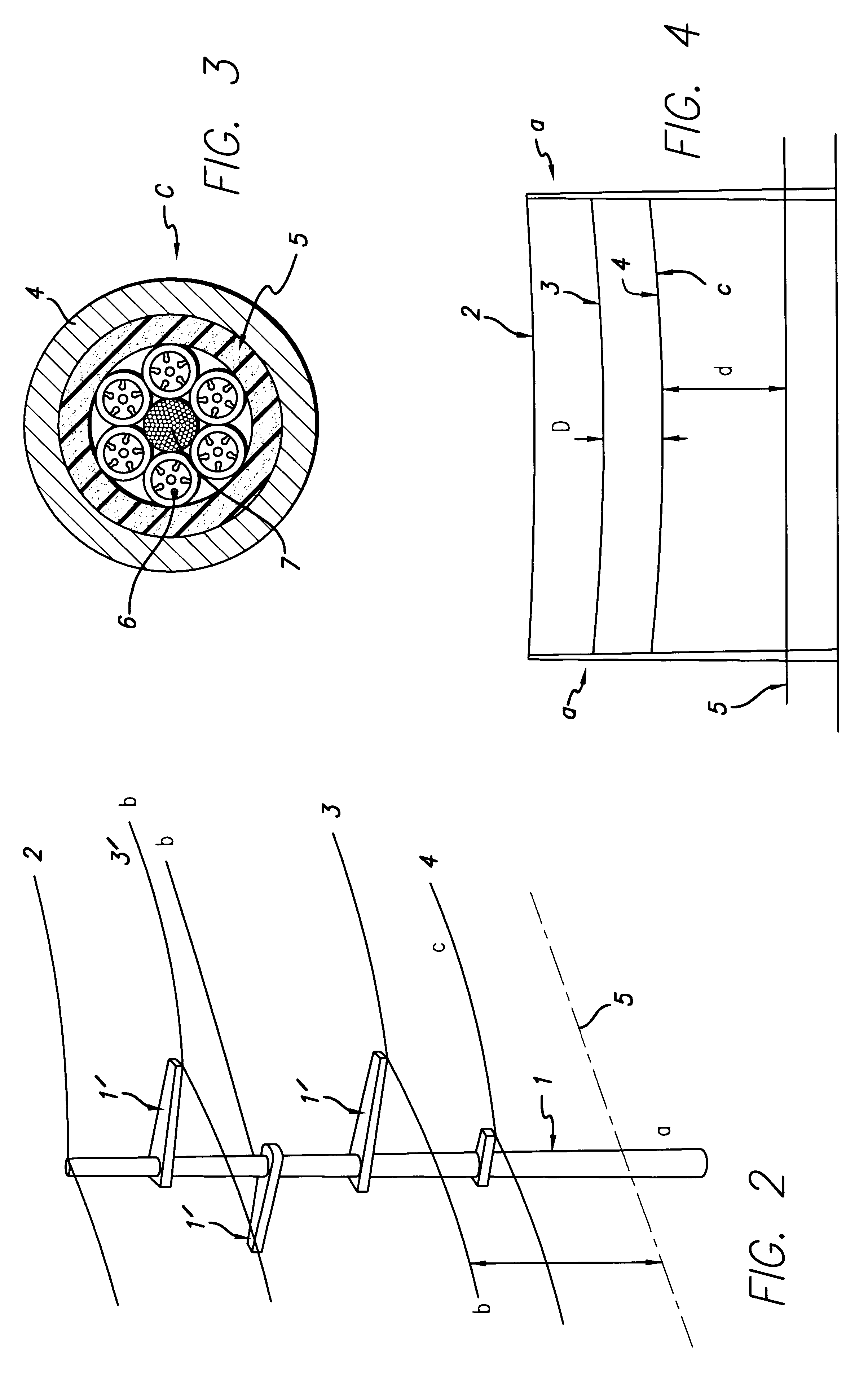
As an illustration of the concepts in this application, the results of the calculations for a 132 Kv three-phase transmission line are presented below. A schematic diagram of the disposition of the towers and the conductors is depicted in FIG. 5. In all cases the line is assumed to be under normal operating conditions, with a positive phases sequence and a current of 100 A per phase, at a frequency of 50 Hz. FIG. 6 is a perspective drawing of a section of the line, including the channeling line, for the assembly depicted in FIG. 5.
The diameters and positions, at mid-span, of the power conductors and the guard wire are summarized in the following table, wherein the X coordinate represents the distance to the axis of the transmission line and the Z coordinate the height above ground level.
The calculated coordinates of the coupling cancellation positions are
In FIG. 7 the electric field intensity has been plotted for a metallic or conductive channeling line placed at the ICCP, while FIG...
PUM
 Abstract
Description
Claims
Application Information