Frequency division multiplexed bar code scanner

a bar code scanner and frequency division technology, applied in instruments, sensing record carriers, sensing by electromagnetic radiation, etc., can solve the problems of inability to do higher speed scanning, more expensive motors, and inability to rotate scanning wheels at a higher rate, so as to improve the bar code reading capability of the scanner, increase the reading range, and accurately determine the distance

Inactive Publication Date: 2001-02-27
SICK AUTO IDENT +1
View PDF8 Cites 17 Cited by
  • Summary
  • Abstract
  • Description
  • Claims
  • Application Information

AI Technical Summary

Benefits of technology

It is a further object of this invention to provide such an improved, frequency division multiplexed bar code scanner which has an enlarged depth of focus without additional moving parts.
It is a further object of this invention to provide such an improved, frequency division multiplexed bar code scanner which employs the same scanner source modulation to increase the reading range and accurately determine the distance.
It is a further object of this invention to provide such an improved, frequency division multiplexed bar code scanner which has a capability to utilize distance measurement information to improve the bar code reading capability of the scanner.
It is a further object of this invention to provide such an improved, frequency division multiplexed bar code scanner which has a capability to intelligently select between lasers to improve the distance measurement accuracy of the scanner.
The invention results from the realization that an improved bar code reader and / or distance measuring system can be effected by amplitude modulating a plurality of laser sources, each with different focal lengths and modulating frequencies, to allow them to share the same optical path thus simply extending the bar code reading range; to use the same modulation to determine the distance by measurement of the phase difference between the outgoing and return laser beam; and to provide the capability of using distance information to improve bar code reading performance.

Problems solved by technology

Thus a faster, more expensive motor is needed to rotate the scanning wheel at a higher rate, or higher speed scanning cannot be done.
Alternatively, additional systems may be used to intelligently switch the lasers at optimum times but this is a more complex and expensive approach.
In another approach a number of separate scanning channels are used each including its own laser, optics, and receiver which increases cost and complexity.
In still another approach mechanical auto focus mechanisms are used but these have many moving parts and are relatively slow, expensive and prone to wear out.

Method used


Image

  • Frequency division multiplexed bar code scanner
  • Frequency division multiplexed bar code scanner
  • Frequency division multiplexed bar code scanner

Examples


Embodiment Construction

Other objects, features and advantages will occur to those skilled in the art from the following description of a preferred embodiment and the accompanying drawings, in which:

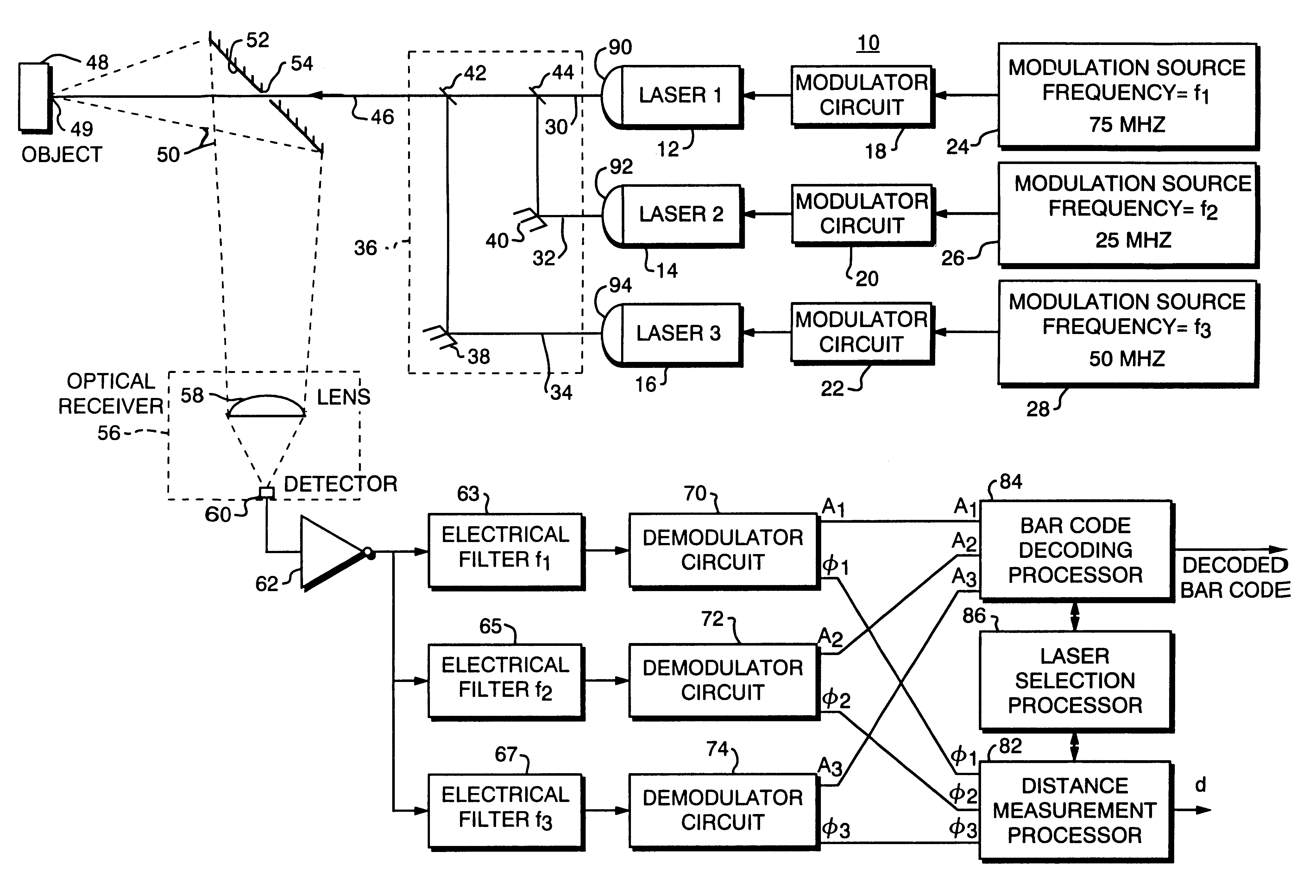
FIG. 1 is a schematic block diagram of a frequency division multiplexed scanner system according to this invention;

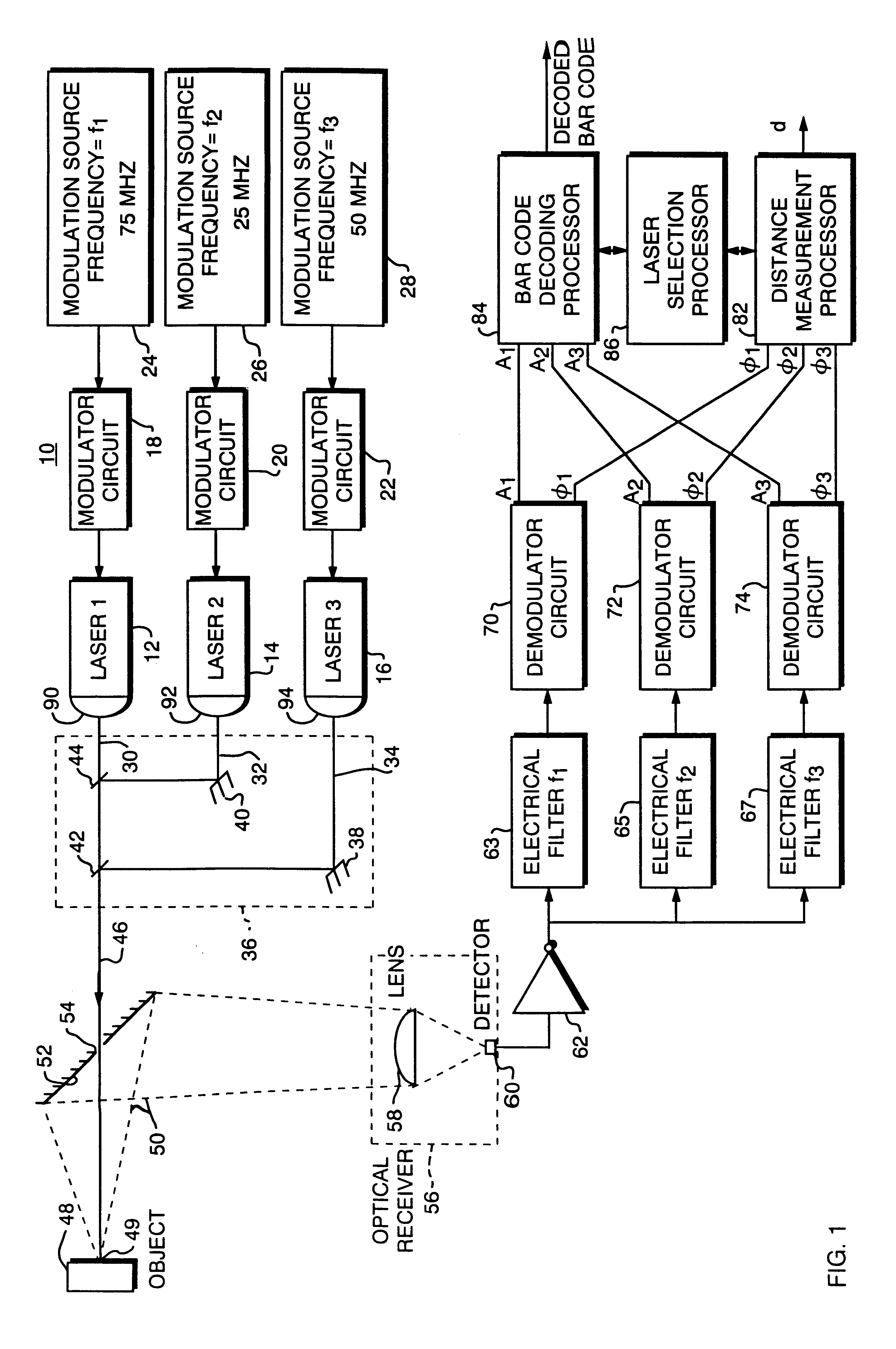
FIG. 2 shows an alternate construction of an implementation of a beam combiner as shown in FIG. 1;

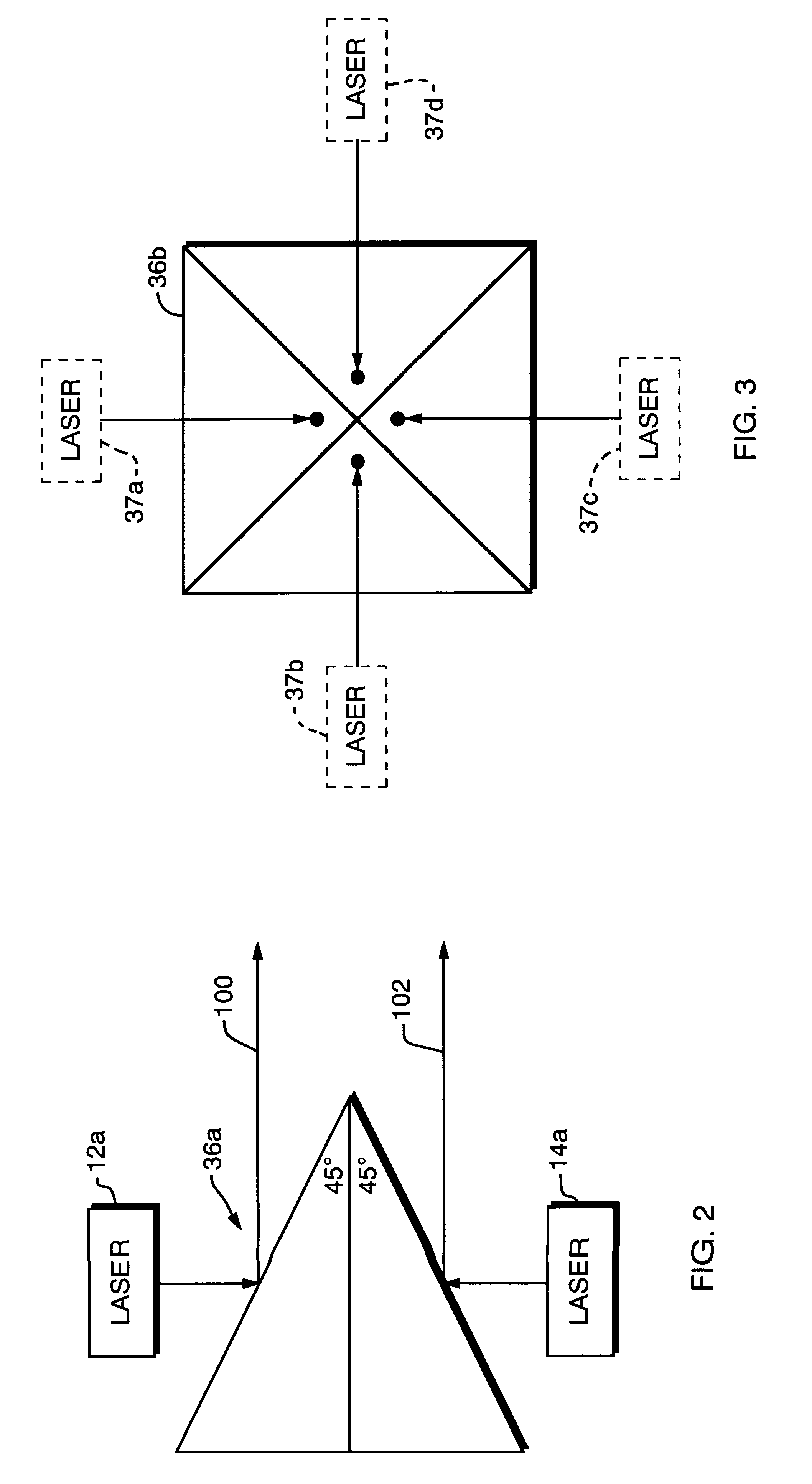
FIG. 3 is a schematic top plan view of an enlarged beam combiner similar to that of FIG. 2;

FIG. 4 is a graphical illustration of the different distant measurement ranges afforded by the different modulation frequencies of each of the lasers of FIG. 1;

FIG. 5 is a schematic graphical representation of the depth of focus range of each of the lasers of FIG. 1;

FIG. 6 is a schematic diagram of one implementation of the demodulators of FIG. 1 for detecting phase information to determine the distance;

FIG. 7 is an illustration of the waveforms that occur at specific points in the circuit of FIG. 6;

FIG. 8 is a g...


PUM


Abstract

A frequency division multiplexed bar code scanner system includes a plurality of radiation sources for simultaneously providing a plurality of source beams, and a modulator circuit for modulating the intensity of each source beam at a different frequency. The source beams are combined and directed along a path to a bar code to be read; the return combined reflected light patterns are amplitude modulated by the bar code and are detected and the amplitude modulation of at least one of these patterns is detected to obtain a representation of the bar code read. The phase shift between the source beam and at least one of the reflected light patterns is used to determine the distance to the barcode bearing object. Distance information may be used to improve barcode reading performance.

Description

This invention relates to a frequency division multiplexed bar code scanner, and more particularly to such a scanner which detects the bar code and the distance of the object bearing the bar code over a large depth of focus.BACKGROUND OF INVENTIONBar code readers are required to read bar codes on objects of a wide variety of sizes wherein the bar codes may be at varying distances from the scanner. This requires a wide range of depths of focus in order to read the bar code clearly and accurately over the entire distance in which they may be presented, typically as much as two meters. In one approach two or more lasers focused at different distances are switched on and off alternately so that only one is on at a time. This requires a switching device to switch between them so that the scan rate is divided by the number of lasers and thus significantly reduced. Thus a faster, more expensive motor is needed to rotate the scanning wheel at a higher rate, or higher speed scanning cannot b...

Claims


Application Information

Patent Timeline
Patent Type & Authority Patents(United States)
IPC IPC(8): G06K7/10
CPCG06K7/10574
Inventor DICKSON, KAREN M.DWINELL, JOHN F.CROLE, PETER V.
Owner SICK AUTO IDENT
Why Eureka
Try Eureka