
Keratometer/pachymeter

a keratometer and a technology of pachymetry, applied in the field of keratometer/pachymeter, can solve the problems of inaccurate method, limited use, and inability to automatically assess the data of the apparatus,

Inactive Publication Date: 2001-02-27
SNOOK RICHARD
View PDF2 Cites 87 Cited by
  • Summary
  • Abstract
  • Description
  • Claims
  • Application Information

AI Technical Summary

Problems solved by technology

In 1896, Gullstrand disclosed the foundation for the current photographic based technology but his apparatus had no provision for automatic data assessment and was limited to a four millimeter diameter zone.
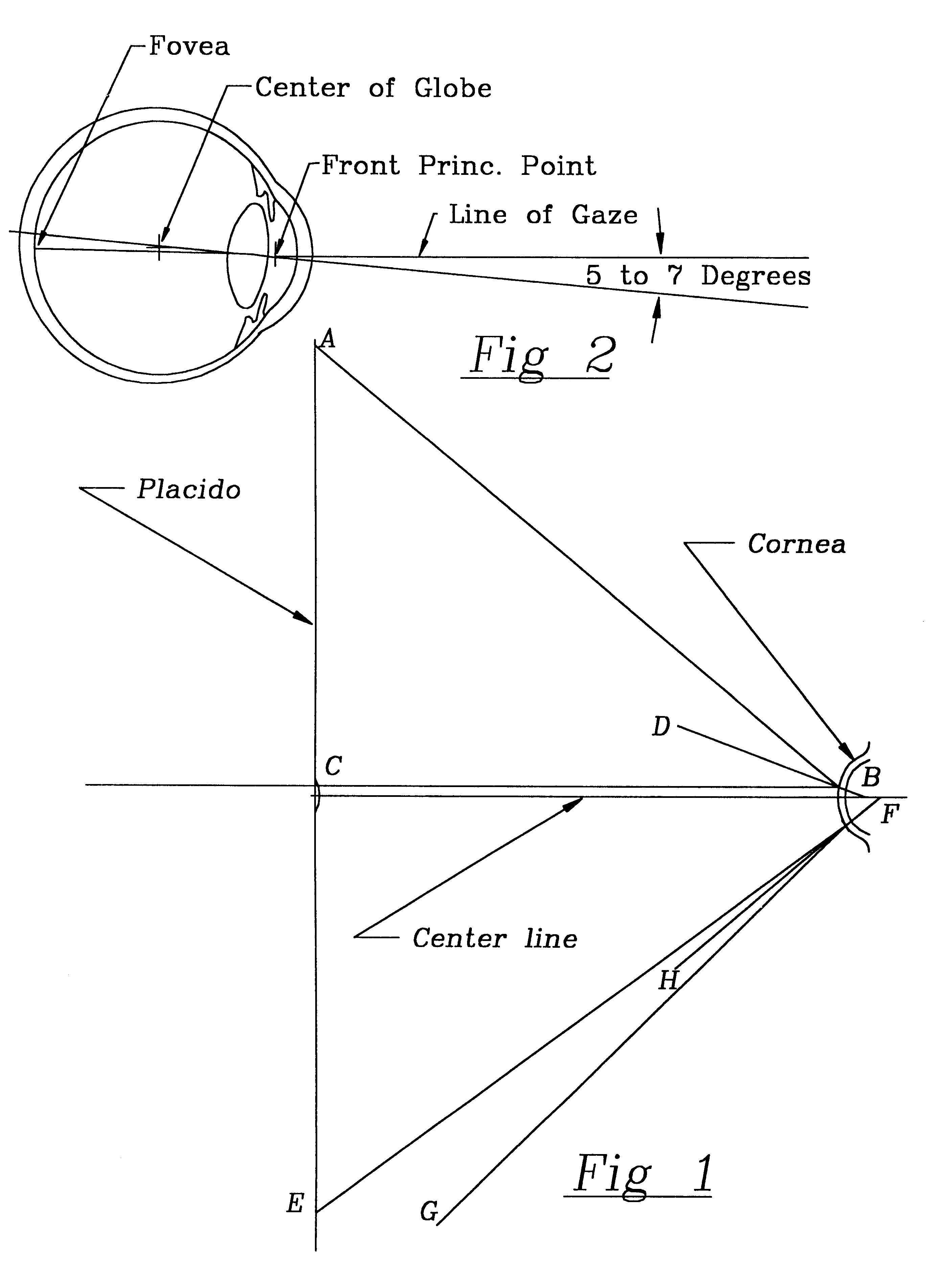
This method is inaccurate because the calibration assumes spherical surfaces or aspheric surfaces centered on the image center of the instrument.
Because the corneal surface is aspheric even in the normal cornea, this multiple fixation technique produces errors which are a function of point of gaze but which are undefinable.
The use of a ground glass focusing screen with the small aperture of the optical system and large linear magnification makes use difficult and requires a darkened room for operation.
Additionally, the method utilizes a separate video / computer analysis step which further degrades accuracy, speed and increases cost of operation.
In fact, these do provide some enhancement of the basic technique from the last century, but they fall short of the goal of exact definition of corneal surface shape and cannot provide thickness information which is imperative for many surgical procedures.
Additionally the prior art devices do not work well in the presence of reflections from objects or lights int he room and do not provide rapid, accurate measurements such as are required fro modern contact lens fitting.
Consequently, the systems are costly, complex, slow and difficult to change if required.
The traditional approach to photogrammetry has bene very software intensive and, thus, quite costly.
The central zone is not resolved because the size of the reflection approaches the inherent resolution of the camera employed and the error of determination increases to infinity at the center of the image being analyzed.
My recent U.S. Pat. Nos. 5,885,767 and 5,735,283 describe apparatus and method for determining the needed information but have an inherent limitation caused by distortion of the projected image points by both surface slope and corneal thickness at the point of reflection.

Method used


Image

  • Keratometer/pachymeter
  • Keratometer/pachymeter
  • Keratometer/pachymeter

Examples


Embodiment Construction

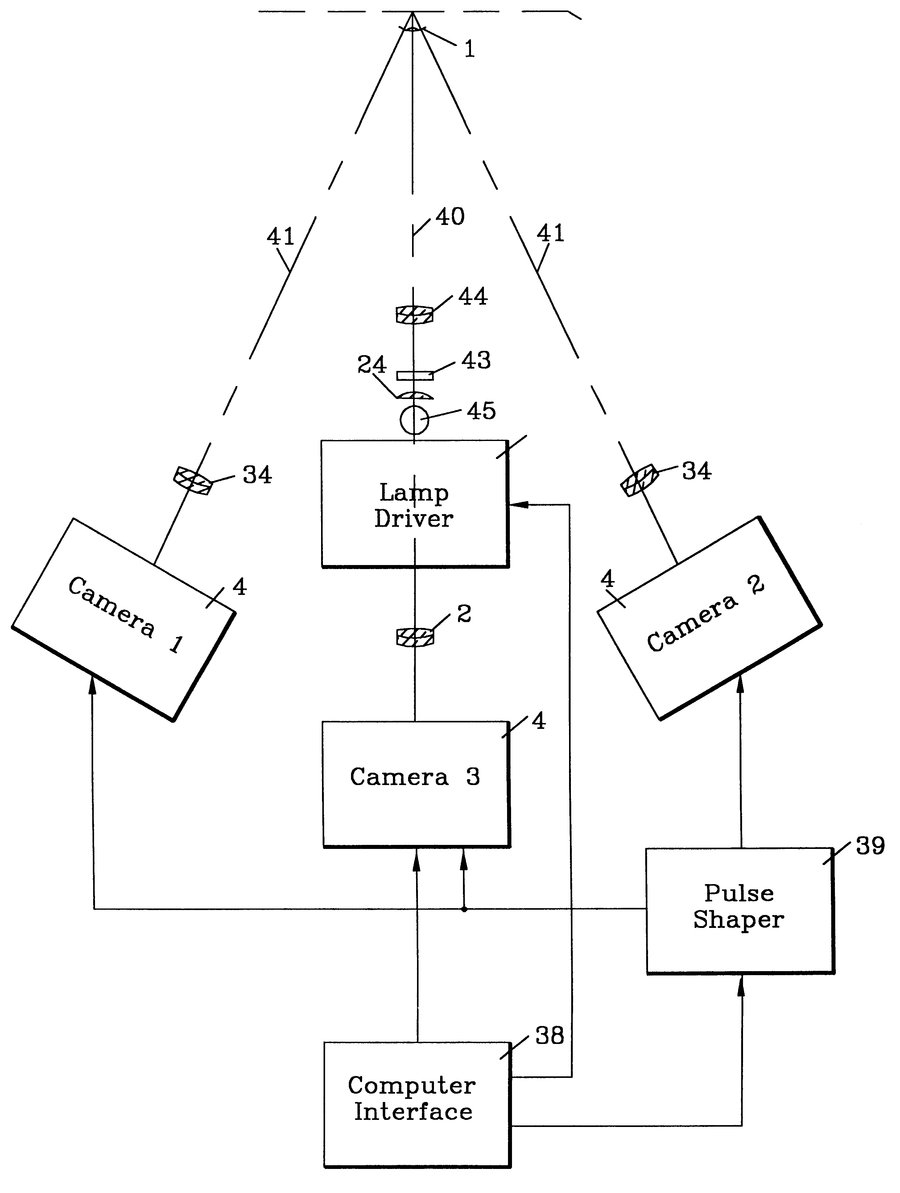
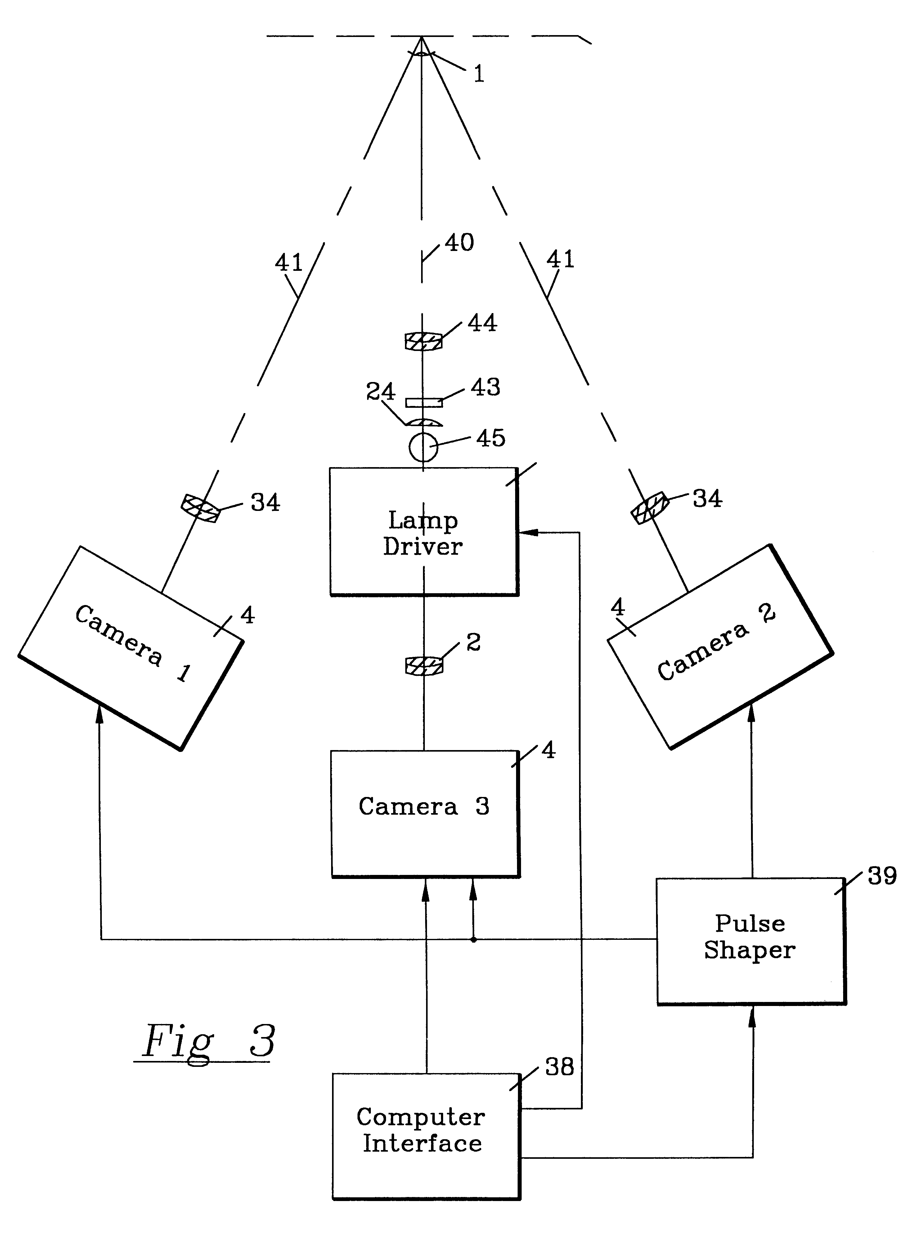
Referring now in more detail and by reference characters to the drawings, and presently to FIG. 2, there is a small area of the retina there is a concentration of the cone type photo-receptor cells which are synapsed on an almost one to one ratio with nerve fibers. This central vision area is termed the fovea. It is at the fovea that the critical vision associated with reading and similar optical tasks takes place. The optical axis of the eye does not coincide with the fovea, but rather is displaced by five to seven degrees. The main light focusing power of the eye is contained in the cornea and the fluid filled anterior chamber in front of the crystalline lens. The surface curvature and thickness of the cornea determines the effective focal length of the optical system and deformation from ideal form results in reduced visual acuity if uncorrected by spectacles, contact lenses or surgical intervention. The lens is mounted in a network of zonules or fibers connected to a muscle syst...


PUM


Abstract

A video Keratometer / Pachymeter comprising an array of illuminated points disposed in concentric circles around the optical axis of a television camera for definition of corneal surface contour by a method similar to the well know Placido, except that the isolated point ring format provides unambiguous back ray trace information to eliminate errors inherent in the prior art, in combination with a projected pattern of discrete points to elicit Tyndall images for definition of both anterior and posterior corneal surface by triangulation using multiple television cameras viewing the reflected and Tyndall images, substraction of a view of the eye with neither pattern superimposed as well as each pattern in sequence for isolation of the data containing points from the general clutter of background pictorial information.

Description

1. Field of the InventionThe present invention relates to improvements in the art of photo-keratometry and pachymetry and, more particularly, to the use of television techniques to ascertain the contour and thickness of the cornea. More specifically, the present invention relates to improvements in the art of photogrammetry where the reflection of a placido or other illuminated target by the surface of the contact cornea is analyzed to determine the surface contour and analysis of steroscopic images of point type Tyndall images for establishing thickness of the cornea. A pachymeter is an instrument for measuring the thickness of the cornea, commonly by ultrasound or optical devices. A keratometer is an instrument for determining the shape of the corneal surface which often uses a placido or other illuminated target which is reflected from the surface to be characterized for surface contour. The present invention measures both the keratorefractive surface shape by a modification of P...

Claims


Application Information

Patent Timeline
IPC IPC(8): A61B3/107A61B3/10
CPCA61B3/1005A61B3/107A61B3/117A61B3/12A61B3/1208A61B3/132A61B3/135A61B3/145
Inventor SNOOK, RICHARD
Owner SNOOK RICHARD
Learn More