Method and Apparatus for Laser Surgery of the Cornea

a laser surgery and cornea technology, applied in the field of corneal surgery, can solve the problem that the importance of the optical quality of the cornea cannot be over-emphasized, and achieve the effect of accurate and safe operation, correction of myopia and/or astigmatism

Inactive Publication Date: 2006-09-28
LAI SHUI T
View PDF62 Cites 60 Cited by
  • Summary
  • Abstract
  • Description
  • Claims
  • Application Information

AI Technical Summary

Benefits of technology

[0055] It is another object of the present invention to provide an improved method for performing a cornea transplant operation. It is another object of the present invention to provide an improved method of making incision

Problems solved by technology

Hence, the importance of the optical quali

Method used


Image

  • Method and Apparatus for Laser Surgery of the Cornea
  • Method and Apparatus for Laser Surgery of the Cornea
  • Method and Apparatus for Laser Surgery of the Cornea

Examples


Embodiment Construction

[0117] Throughout this description, the preferred embodiment and examples shown should be considered as exemplars, rather than limitations on the method and apparatus of the present invention.

[0118] Background Information

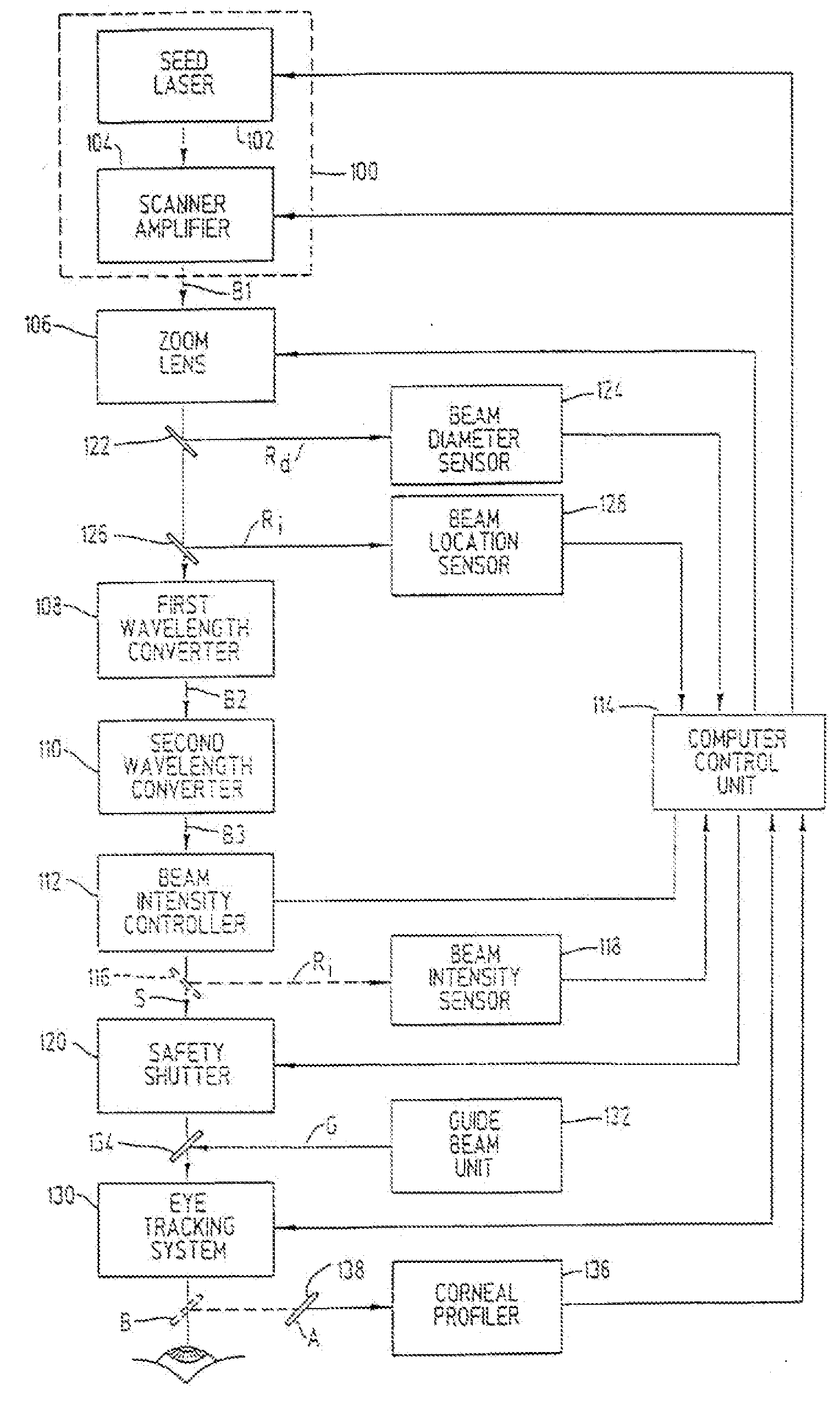
[0119] The laser apparatus and system disclosed in this invention is for achieving two principal objectives:

[0120] (1) The damage zone underneath the material ablated by the present laser system must be substantially reduced in comparison to prior art laser systems.

[0121] (2) For each laser pulse deposited on the cornea, a definite predetermined depth of tissue is to be ablated. The ablated depth per laser pulse must be controllable and about 0.2 microns or less, and preferably about 0.05 microns or less.

[0122] A brief discussion on the mechanism of the ablation process is useful to understand how the stated objectives can be achieved by the teaching of the present invention. It is a well-known fact that laser ablation can occur when the laser beam intensity is...


PUM

PropertyMeasurementUnit
Lengthaaaaaaaaaa
Timeaaaaaaaaaa
Forceaaaaaaaaaa

Abstract

A laser-based method and apparatus for corneal surgery. The present invention is intended to be applied primarily to ablate organic materials, and human cornea in particular. The invention uses a laser source which has the characteristics of providing a shallow ablation depth (0.2 microns or less per laser pulse), and a low ablation energy density threshold (less than or equal to about 10 mJ/cm.sup.2), to achieve optically smooth ablated corneal surfaces. The preferred laser includes a laser emitting approximately 100-50,000 laser pulses per second, with a wavelength of about 198-300 nm and a pulse duration of about 1-5,000 picoseconds. Each laser pulse is directed by a highly controllable laser scanning system. Described is a method of distributing laser pulses and the energy deposited on a target surface such that surface roughness is controlled within a specific range. Included is a laser beam intensity monitor and a beam intensity adjustment means, such that constant energy level is maintained throughout an operation. Eye movement during an operation is corrected for by a corresponding compensation in the location of the surgical beam. Beam operation is terminated if the laser parameters or the eye positioning is outside of a predetermined tolerable range. The surgical system can be used to perform surgical procedures including removal of corneal scar, making incisions, cornea transplants, and to correct myopia, hyperopia, astigmatism, and other corneal surface profile defects.

Description

CROSS REFERENCE TO RELATED APPLICATIONS [0001] This application is a continuation of U.S. application Ser. No. 10 / 801,891, now published as 2004 / 0199150, which is a continuation of U.S. patent application Ser. No. 09 / 799,412, filed Mar. 5, 2001, now U.S. Pat. No. 6,706,036, which is a divisional of U.S. patent application Ser. No. 09 / 130,547 filed Aug. 6, 1998, now U.S. Pat. No. 6,210,401 which is a continuation of patent application Ser. No. 07 / 788,424, filed on Nov. 6, 1991, all of which are incorporated by reference herein in their entirety. Priority is claimed to each of these applications.BACKGROUND OF THE INVENTION [0002] 1. Field of the Invention [0003] This invention relates to methods of, and apparatus for, surgery of the cornea, and more particularly to a laser-based method and apparatus for corneal surgery. [0004] 2. Related Art [0005] The concept of correcting refractive errors by changing the curvature of the eye was brought forth early on, as illustrated in the notable...

Claims


Application Information

Patent Timeline
IPC IPC(8): A61B18/18A61B17/00A61B18/20A61F9/007A61F9/008A61F9/01B23K26/00B23K26/03B23K26/04B23K26/06B23K26/42G02B26/10G02F1/37H01S3/00H01S3/06H01S3/101H01S3/23
CPCA61B2017/00694A61F9/00804A61F9/00814A61F2009/00846A61F2009/00872A61F2009/00897B23K26/0096B23K26/03B23K26/032B23K26/04B23K26/06B23K26/0635B23K26/0648B23K26/0652B23K26/0665B23K26/425G02B26/10G02F1/37H01S3/005H01S3/06H01S3/101H01S3/235B23K26/043B23K26/704B23K26/0624
Inventor LAI, SHUI T.
Owner LAI SHUI T
Why Eureka
Try Eureka