Buoyancy engine for capturing undersea gas

Inactive Publication Date: 2001-03-06
DE SHON DENIS ALAN
View PDF4 Cites 25 Cited by
  • Summary
  • Abstract
  • Description
  • Claims
  • Application Information

AI Technical Summary

Benefits of technology

It is another object of the invention to provide apparatus of this character that is simple in construction and operation.
It is a

Problems solved by technology

But, none have addressed the employment of a buoyancy engine in a subsea enviro

Method used


Image

  • Buoyancy engine for capturing undersea gas
  • Buoyancy engine for capturing undersea gas
  • Buoyancy engine for capturing undersea gas

Examples


Embodiment Construction

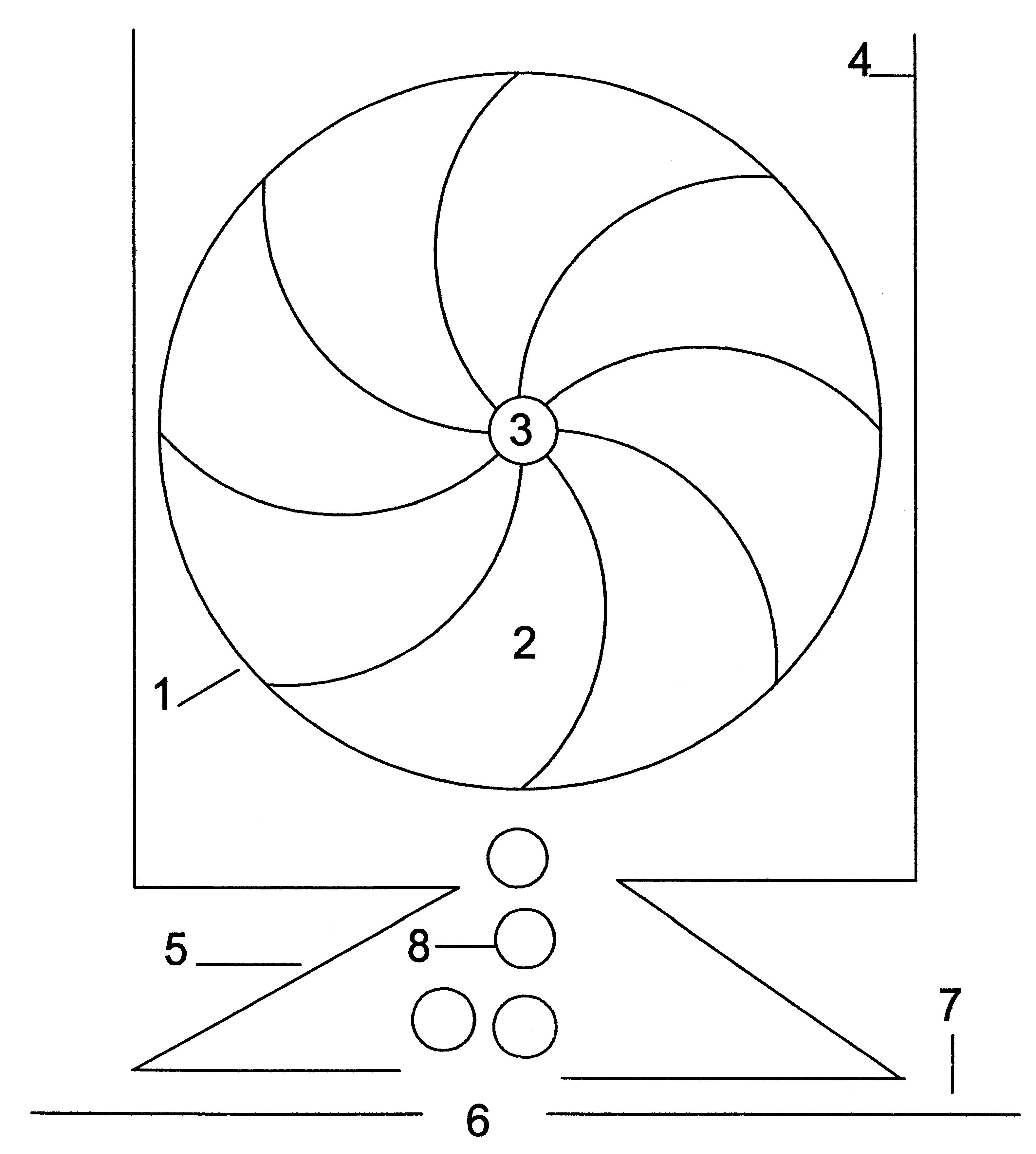
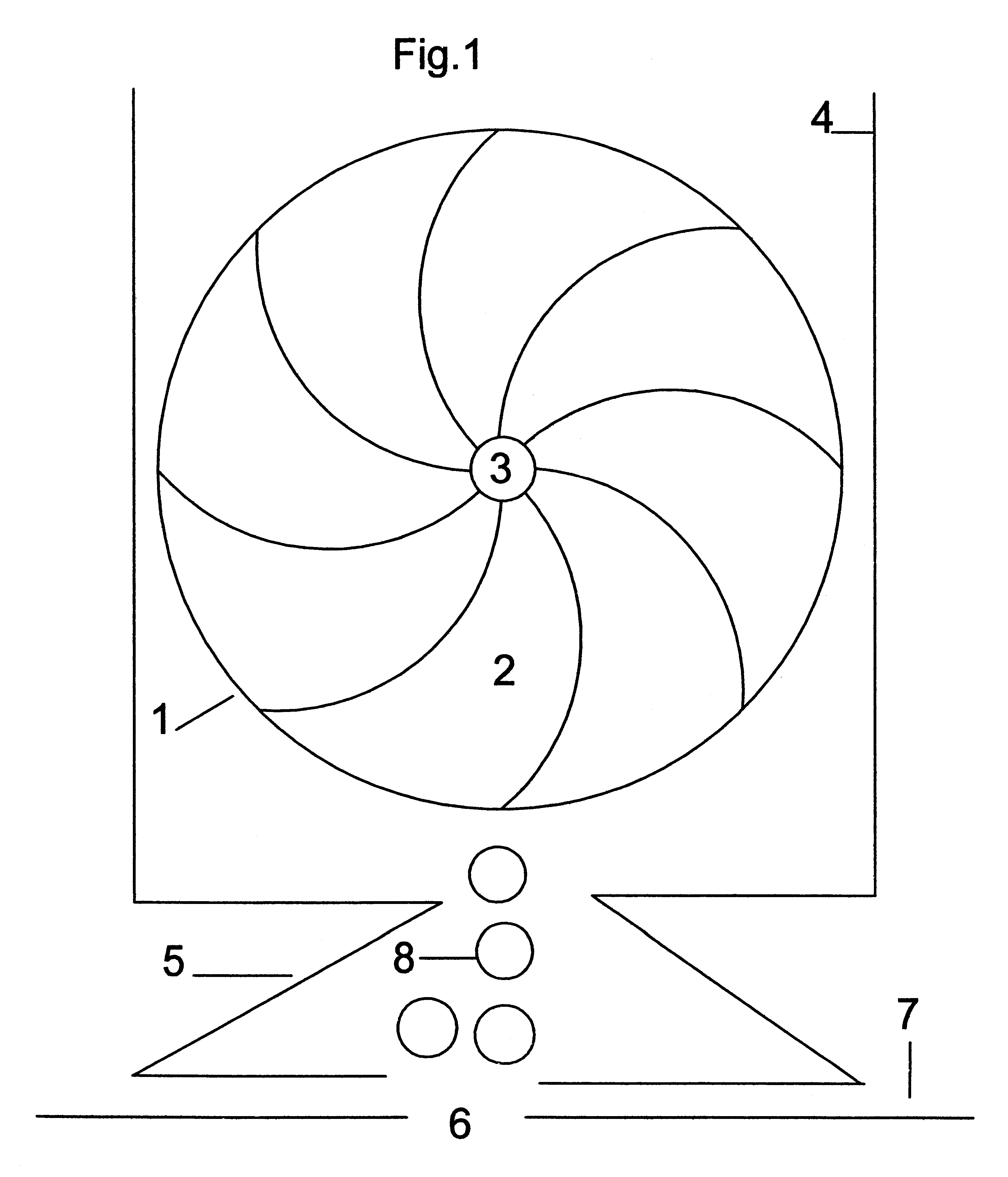
Referring to the drawings, in FIG. 1 there is shown apparatus embodying the present invention. A ring (1), containing gas holding spaces (2) is attached to a driveshaft (3) which is rotably mounted in the wall (4) of the apparatus. Below the ring is a collector (S) which is positioned above a gas emitting sea vent (6) on the sea floor (7). The gas (8) is directed into the apparatus at the 180 degree position of the ring. The buoyant force of the gas (8) causes the ring (1) to rotate upward, imparting a rotational force to the driveshaft (3). Gas, (8) having expended its buoyant force within the apparatus, is discharged at the 360 degree point of the ring.

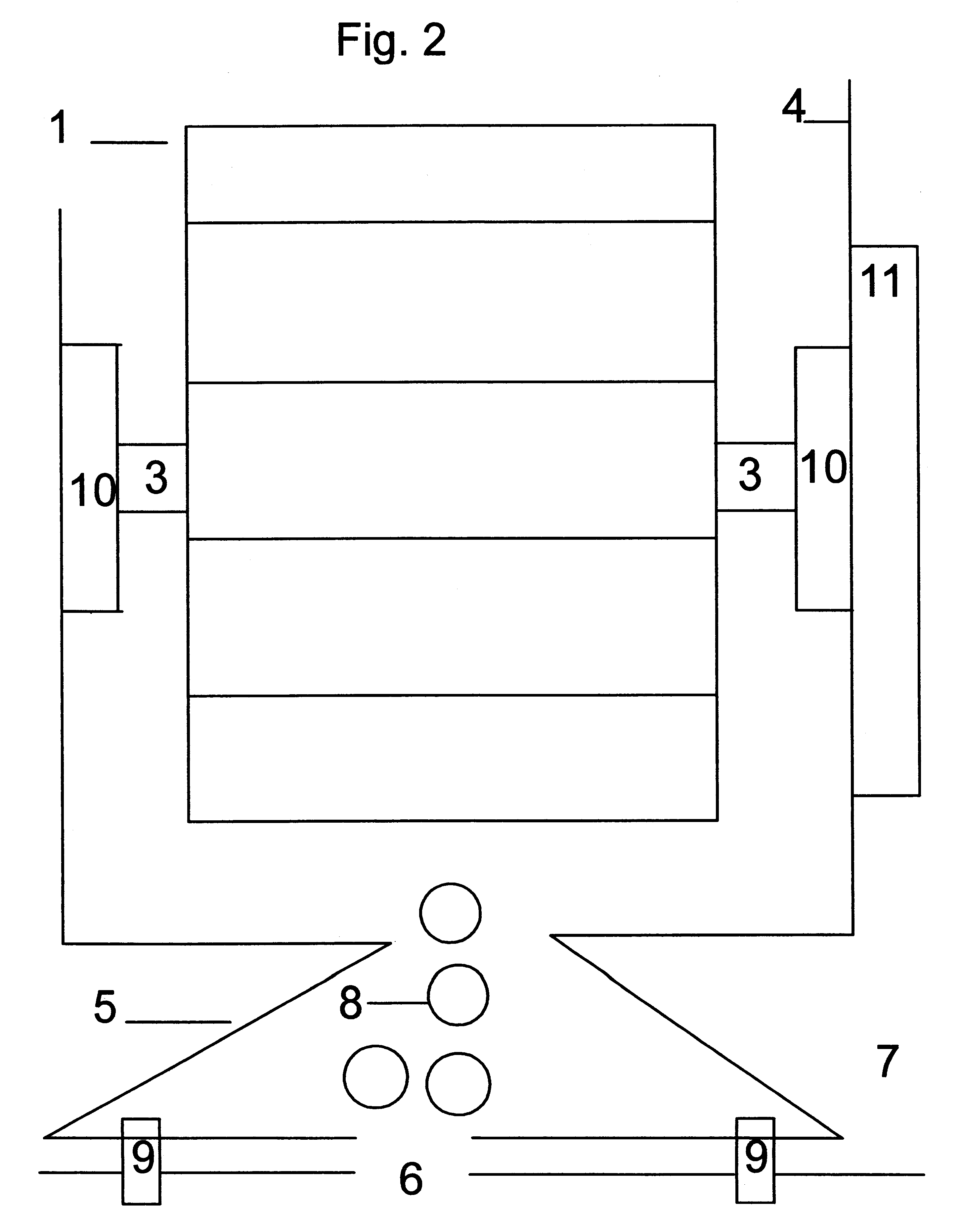
In FIG. 2, are shown the mounting bolts (9) which attach the apparatus to the sea floor. The ring (1) is attached to the driveshaft (3) and is mounted in sealed bearings (10) in the wall (4) of the apparatus. The driveshaft (3) is connected to, and rotates, the electric generator (11) producing electricity which is directed to the d...


PUM


Abstract

A buoyancy engine is mounted on the sea floor above a natural gas vent. The engine captures emitted gas in a ring containing gas holding spaces. The gas imparts buoyant energy which is converted into rotational force as the gas ascends thru the apparatus, and the ring rotates. The ring is attached to a driveshaft mounted on bearings in the walls of the apparatus, and turns an electric generator.

Description

1. Field of the InventionThis invention relates generally to buoyancy engines, and, more particularly, to one which is disposed on the sea floor to capture gas emitted by the earth. Buoyant gas is captured in the apparatus, which rotates a generator to convert the buoyant energy into electricity.2. Description of the Prior ArtThere have been various designs for buoyancy engines which show alternative approaches to capturing a gas in a liquid environment.But, none have addressed the employment of a buoyancy engine in a subsea environment to capture naturally occurring gas emissions from sea vents and the like.The invention is a buoyancy engine comprised of a plurality of gas holding spaces incorporated into a ring attached to a driveshaft which is supported on sealed bearings in the walls of the apparatus. The apparatus is mounted on the sea floor above vents in the sea floor. Gas, naturally occurring from pressures within the earth, spews from these vents. This gas is directed into ...

Claims


Application Information

Patent Timeline
IPC IPC(8): F03B17/00F03B17/02
CPCF03B17/02F05B2240/24Y02E10/20
Inventor DE SHON, DENIS ALAN
Owner DE SHON DENIS ALAN
Why Eureka
Try Eureka