Motor protection for a powered door system

Inactive Publication Date: 2001-03-06
WESTINGHOUSE AIR BRAKE CO
View PDF4 Cites 35 Cited by
  • Summary
  • Abstract
  • Description
  • Claims
  • Application Information

AI Technical Summary

Benefits of technology

It is therefore one of the primary objects of the present invention to provide

Problems solved by technology

Powered door systems for use on transit vehicles, elevators and the like typically experience very heavy usage which may place severe demands on the motors that open and close the doors.
Such motors are generally undersized due to size and weight constraints.
The friction which the doors experience when they are moved between open and closed positions may increase due to a number of factors including temperature, loss of lubricant, galling of load bearing surfaces, etc.
In such

Method used


Image

  • Motor protection for a powered door system
  • Motor protection for a powered door system
  • Motor protection for a powered door system

Examples


Embodiment Construction

, particularly, when the detailed description is taken in conjunction with the attached drawing figures and with the appended claims.

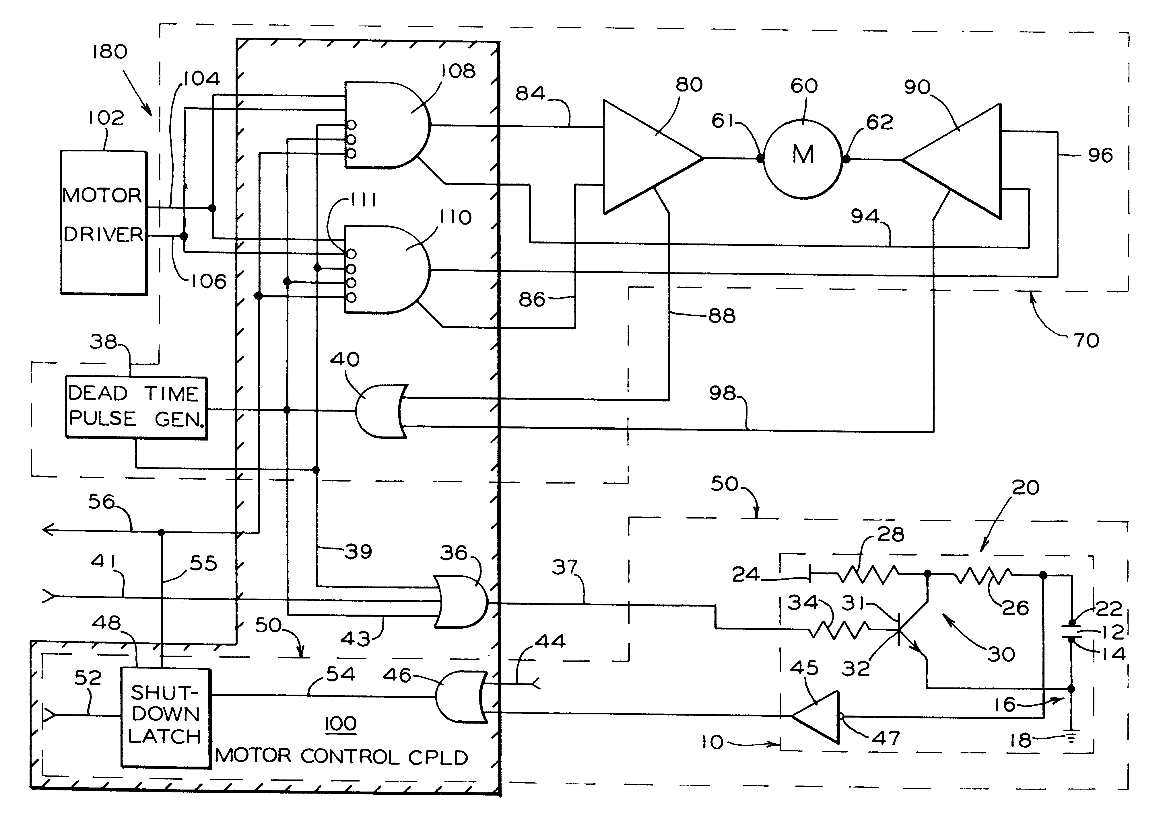
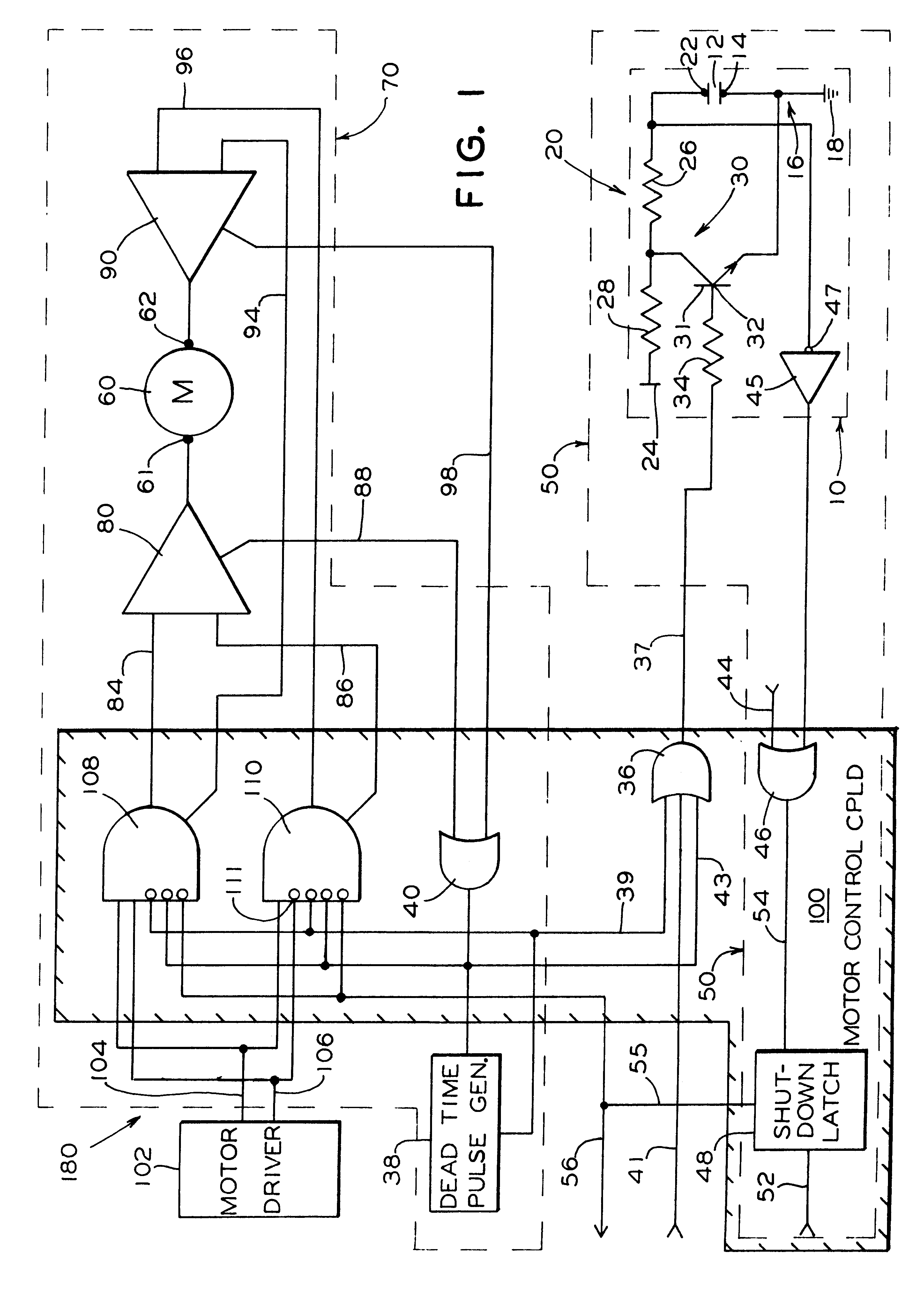
FIG. 1 is a block diagram of a motor protection circuit for a DC motor powered by an H-bridge amplifier;

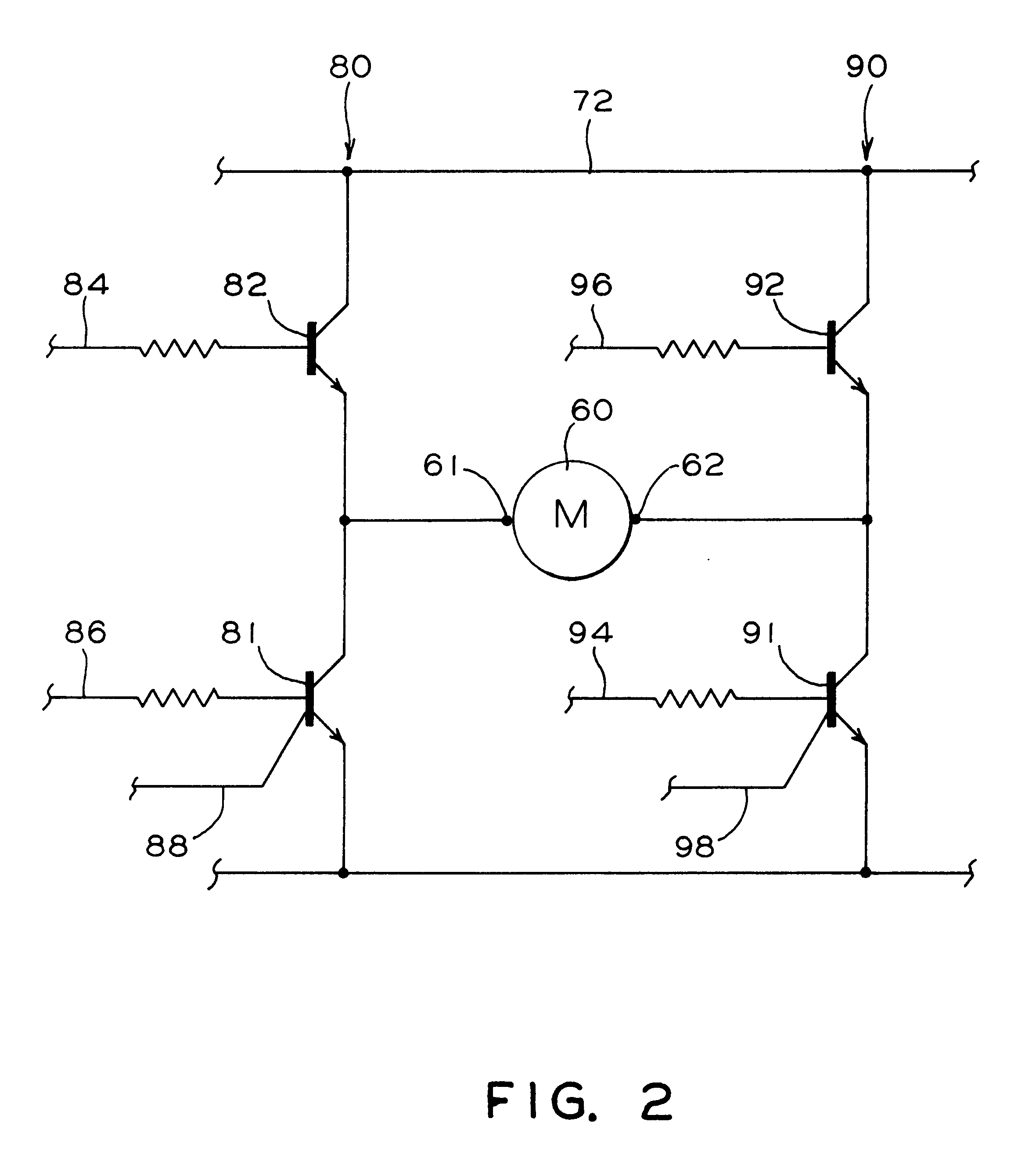
FIG. 2 is a schematic diagram illustrating such an H-bridge amplifier; and

FIG. 3 is a block diagram of a motor protection circuit for a brushless DC motor powered by a pulse width modulated motor drive amplifier.

BRIEF DESCRIPTION OF THE PRESENTLY PREFERRED AND VARIOUS ALTERNATIVE EMBODIMENTS OF THE INVENTION

Prior to proceeding to the much more detailed description of the present invention, it should be noted that identical components which have identical functions have been identified with identical reference numerals throughout the several views illustrated in the drawing figures for the sake of clarity and understanding of the invention.

Reference is now directed to FIG. 1 which illustrates an electric motor and motor control system, generally desig...


PUM


Abstract

A motor protection circuit for an electric motor driven by a pulse width modulated amplifier. It has a capacitor and a first conduction path connected to a first terminal of the capacitor and connectable to a first conductor. It also has a second conduction path connected to the second capacitor terminal and connectable to a second conductor. There is a DC voltage difference between the first conductor and the second conductor. There is a third conduction path between the first terminal and the second terminal. The third conduction path having a resistance which is lower than the resistance of the first conduction path plus the resistance of the second conduction path. The third conduction path passes through a switch which has an input connection to be opened and closed thereby. The input connection is for receiving a signal indicating a motor overload condition, whereby the capacitor discharge switch is closed when the signal indicates the motor overload condition and the capacitor discharge switch is opened when the signal does not indicate the motor overload condition. A charge on the capacitor increases when the signal does not indicate the motor overload condition and the charge on the capacitor decreases when the signal indicates the motor overload condition. The circuit also has a voltage comparator receiving the voltage of the capacitor. The voltage comparator produces a signal for shutting down the motor.

Description

The present invention relates, in general, to motor protection circuits and, more particularly, the instant invention relates to motor protection for transit vehicle door systems and / or elevator doors.Powered door systems for use on transit vehicles, elevators and the like typically experience very heavy usage which may place severe demands on the motors that open and close the doors. Such motors are generally undersized due to size and weight constraints. Consequently, motor protection circuits are generally necessary to prevent burn out of such motors.The friction which the doors experience when they are moved between open and closed positions may increase due to a number of factors including temperature, loss of lubricant, galling of load bearing surfaces, etc. In such applications, the doors may be quite massive and may be required to move rapidly between open and closed positions. This places a heavy demand on the motors to overcome the inertia of the doors when accelerating an...

Claims


Application Information

Patent Timeline
IPC IPC(8): H02H7/08H02H6/00
CPCH02H7/0838H02H6/00
Inventor CALAMATAS, PHILIP J.
Owner WESTINGHOUSE AIR BRAKE CO
Why Eureka
Try Eureka