Circuit for dynamic switching of a buffer threshold

a buffer threshold and circuit technology, applied in the field of circuitry, can solve the problems of rapid signal transmission, undesirable situation, signal accuracy suffers,

Inactive Publication Date: 2001-03-06
SEMICON COMPONENTS IND LLC
View PDF10 Cites 10 Cited by
  • Summary
  • Abstract
  • Description
  • Claims
  • Application Information

AI Technical Summary

Problems solved by technology

It is often the case, however, that when transmission rates increase, signal accuracy may suffer.
In particular, it is well known that rapid signal transmission may be accompanied by signal bounce.
Either situation is undesirable.
Clearly, unexpected changes in logic values are not desirable.
This problem is more likely to occur as transmission rates are increased.
However, the gain in increased transmission rate is often undermined by an increase in signal noise.
As transistors become increasingly smaller in order to achieve the faster transmission rates of interest, the signal bounce that occurs with the rapid switching often creates reflections in transmission media,

Method used


Image

  • Circuit for dynamic switching of a buffer threshold
  • Circuit for dynamic switching of a buffer threshold
  • Circuit for dynamic switching of a buffer threshold

Examples


Embodiment Construction

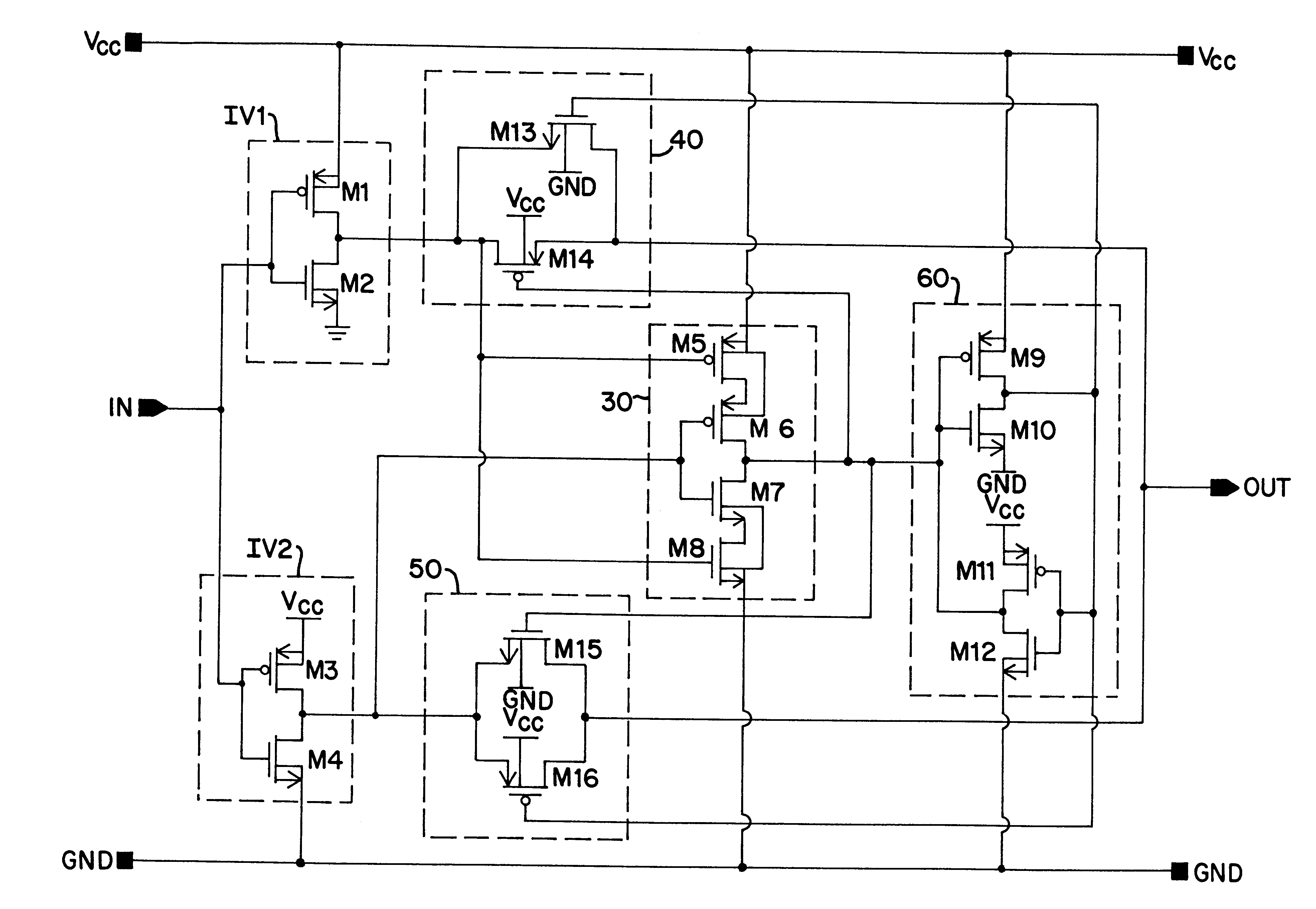
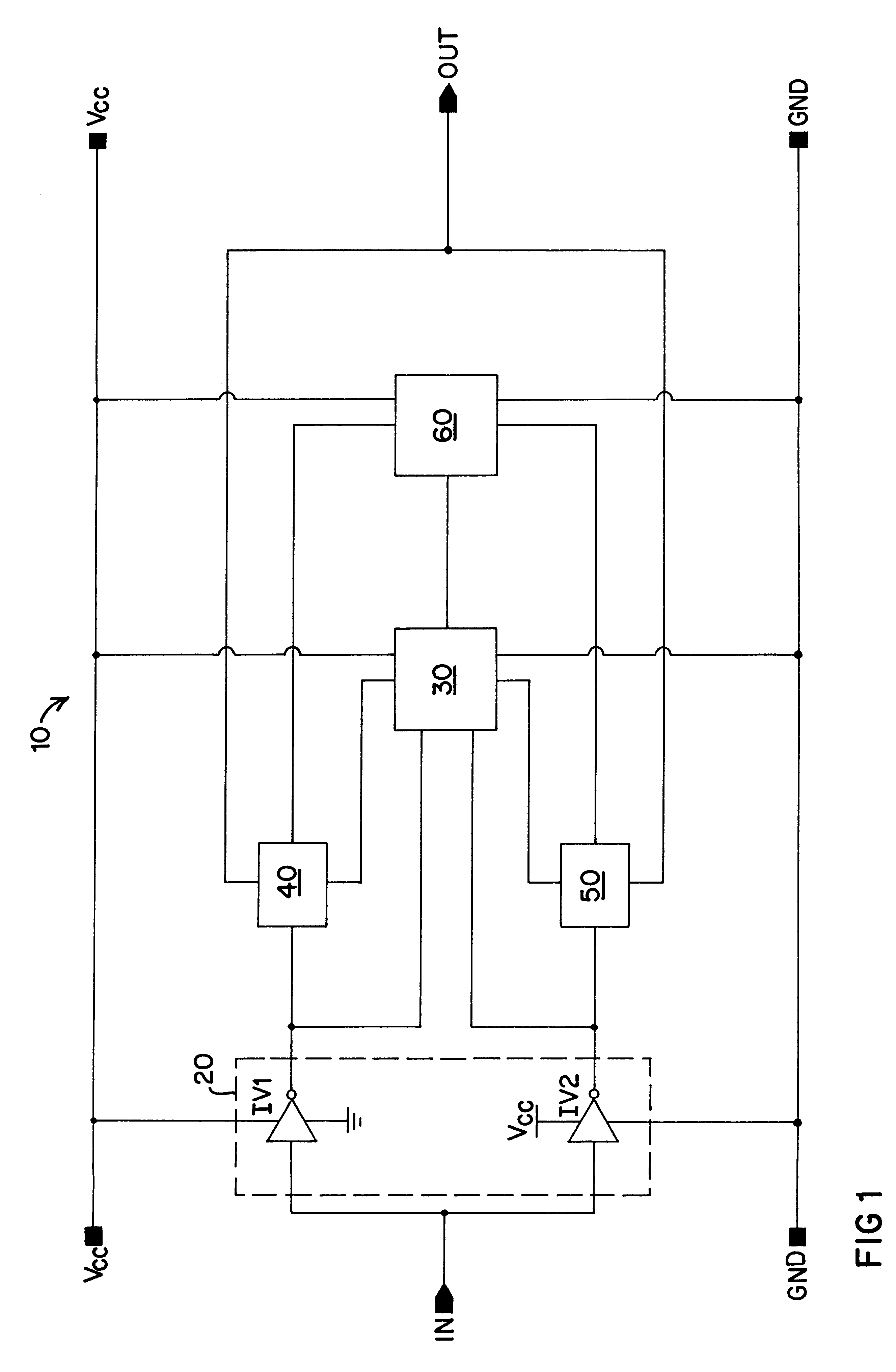
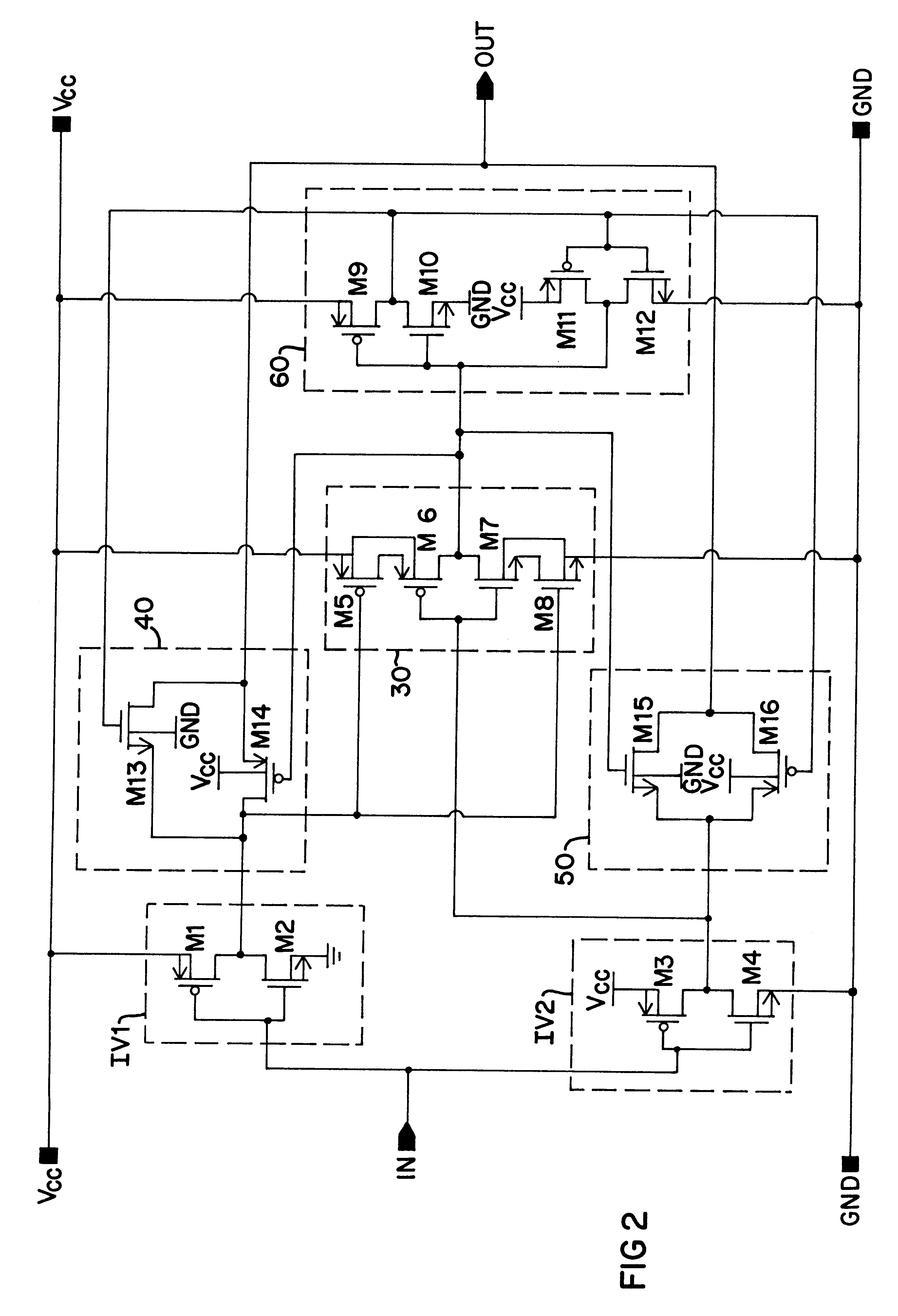
A simplified illustration of a buffer circuit 10 of the present invention having dynamic threshold control is shown in FIG. 1. The buffer circuit 10 includes an input section 20 formed of a first input device represented by first inverter IV1 and a second input device represented by inverter IV2, each of which acts essentially as a separate sub-buffer circuit. Although shown in FIG. 1 as two single inverters, it is to be understood that the first and second input devices may be formed by a set of inverters or other suitable switching devices. The first inverter IV1 and the second inverter IV2 are each supplied by a high-potential power rail Vcc and a low-potential power rail GND, with their inputs designed to receive an input signal at input node IN for transmission to extended circuitry coupled to the buffer 10 at output node OUT. The buffer circuit 10 also includes a logic circuit 30 having as inputs the outputs of the first inverter IV1 and the second inverter IV2. Supply rails V...


PUM


Abstract

A buffer circuit for providing dynamic threshold control. The buffer circuit includes a pair of input inverters designed with different skewed threshold potential characteristics. The outputs of the skewed inverters are directed to a logic circuit designed to select either the faster or the slower signal received from the two inverters for transmission to passgate devices coupled to the respective inverters. Only one of the passgate devices is enabled to ensure that only one of the output signals from the two inverters is propagated through the buffer. A latch is preferably connected between the logic circuit and the two passgate devices to maintain the states of the inverters and the logic circuit. The circuit can be designed to define the threshold potential at which switching will occur so as to reduce propagation delay or increase it as desired. It is therefore possible using the circuit to increase transmission rates with minimal affect on signal noise.

Description

1. Field of the InventionThe present invention relates to circuitry for adjusting the rate at which signal transitions occur. In particular, the present invention relates to buffer circuits providing faster switching. More particularly, the present invention relates to circuitry that dynamically adjusts the threshold potential at which signal transitions occur.2. Description of the Prior ArtInput buffers are used to transfer electrical signals of desired amplitude and strength. Input buffers are used to ensure that those electrical signals are transferred as accurately and as quickly as possible. It is often the case, however, that when transmission rates increase, signal accuracy may suffer. In particular, it is well known that rapid signal transmission may be accompanied by signal bounce. That bounce is the noise or ringing associated with the undershoot and overshoot of a final steady state logic high or logic low signal that occurs in the transition between high and low. The dif...

Claims


Application Information

Patent Timeline
IPC IPC(8): H03K19/00H03K19/017H03K19/01
CPCH03K19/0027H03K19/01707H03K19/00
Inventor MORRILL, DAVID P.
Owner SEMICON COMPONENTS IND LLC
Why Eureka
Try Eureka