Multifunction printed-circuit antenna

a printed circuit and antenna technology, applied in the field of multi-functional printed circuit antennas, can solve problems such as uncertified performance characteristics

Inactive Publication Date: 2001-03-06
THOMSON CSF SA
View PDF5 Cites 39 Cited by
  • Summary
  • Abstract
  • Description
  • Claims
  • Application Information

AI Technical Summary

Problems solved by technology

Furthermore, when it is proposed to obtain the GLONASS function throu

Method used


Image

  • Multifunction printed-circuit antenna
  • Multifunction printed-circuit antenna
  • Multifunction printed-circuit antenna

Examples


Embodiment Construction

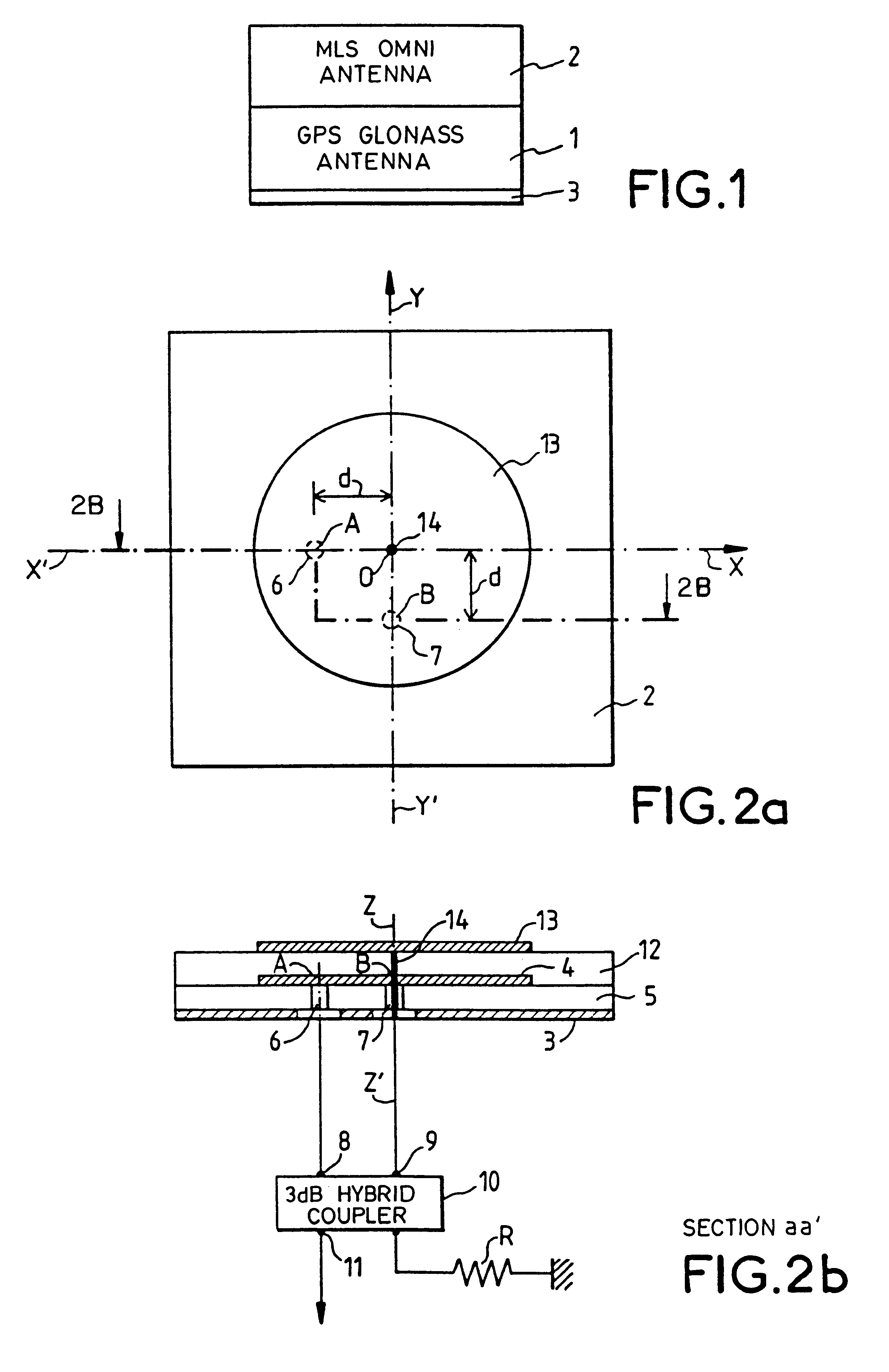
The antenna according to the invention which is shown according to the schematic diagram of FIG. 1 consists of two superimposed antenna structures referenced 1 and 2 on top of the same ground plane 3.

The antenna structure 1 is suited to the reception of the L band signals of the GPS or GLONASS system while the antenna structure 2 is suited to the reception of the signals of the Omni MLS system.

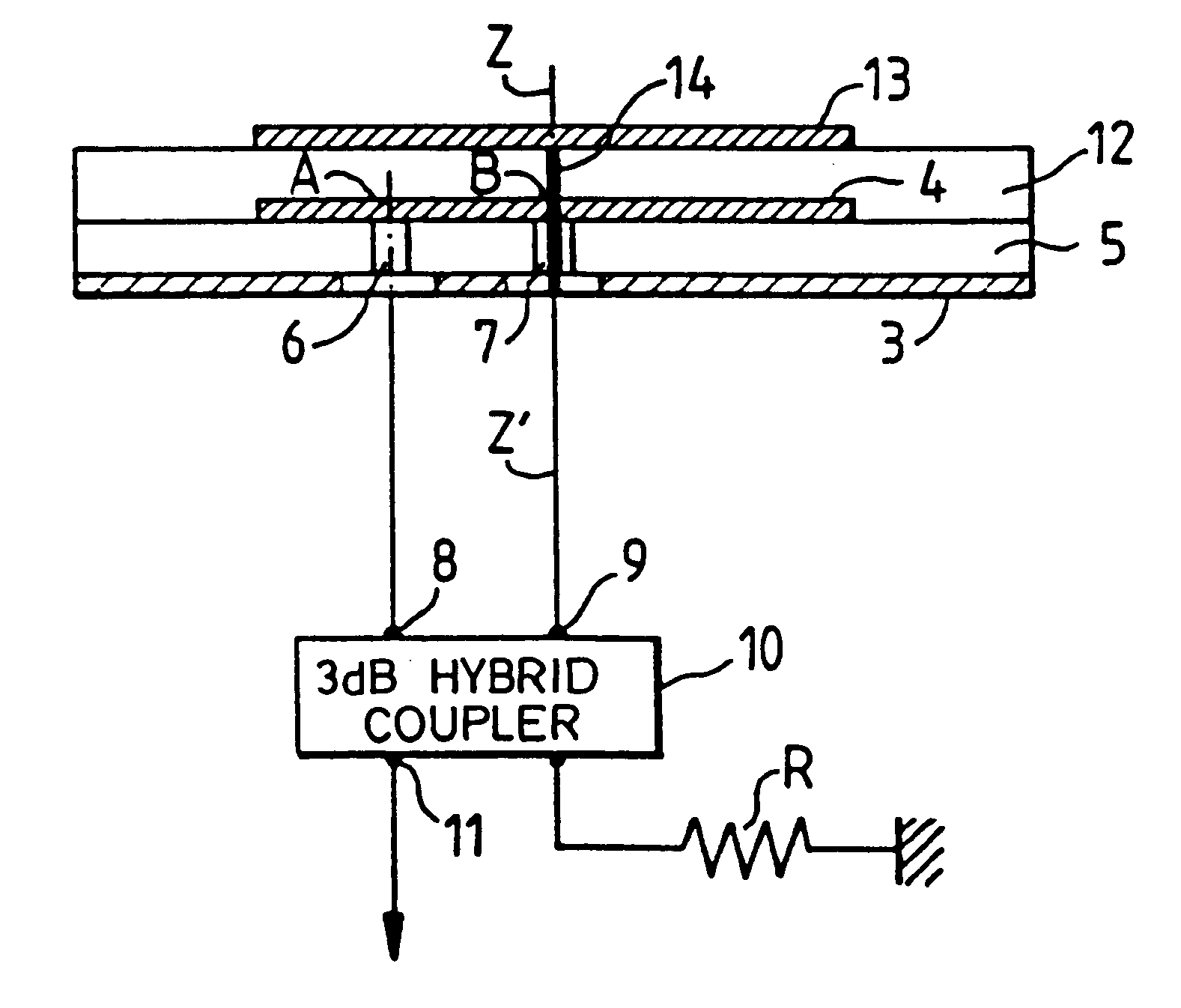
The antenna structure 1 is shown in FIGS. 2a and 2b in a top view and a profile view along the section aa'. It has a first patch consisting of a conductive film 4 deposited on the upper face of a dielectric substrate 5 whose lower face is parallel to the upper face and is entirely metallized to form a ground plane 3. The conductive film 4 has a circular shape in order to obtain a reception pattern with a symmetry generated by revolution.

The electromagnetic field received by the antenna inside the dielectric substrate is propagated according to the TM.sub.100 and TM.sub.001 resonance modes. Coa...


PUM


Abstract

The multifunction printed-circuit antenna is designed for the reception of radioelectric waves sent by the GPS, GLONASS and MLS radio navigation systems. It comprises first, second and third circular patches that are parallel to one another and superimposed in this order above one and the same ground plane that is parallel to them, the centers of the patches being aligned on one and the same axis z'z perpendicular to the plane of the three patches, the patches being separated from one another by thicknesses of a substrate-forming dielectric material for each of the patches. The first and second patches form, with the ground plane, the antenna structure for the reception of the GPS, GLONASS waves. The MLS antenna reception structure is formed by the third and second patches. The second patch also serves as a ground plane for the MLS antenna structure. The third patch of the MLS structure has a diameter smaller than that of the first and second patches of the GPS, GLONASS structure, and the surface dimensions of the dielectric substrate between the third and second patches are smaller than those of the first and second patches. Application to GPS/GLONASS, MLS antennas.

Description

1. Field of the InventionThe present invention forms part of the general framework of the combining of radioelectric functions in aircraft.It can be applied especially to the making of an aircraft antenna according to the known technology of multilayer printed circuits combining, on the one hand, the functions of satellite localization of systems working in the L band of the radioelectric frequencies, known as the Global Positioning System or GPS L1 and the Global Navigation Satellite System or GLONASS and, on the other hand, the landing assistance function in the C band of radioelectric frequencies working in the Omni MLS or Microwave Landing System.2. Description of the Prior ArtAt present, the antennas related to these functions are distinct and have different technologies. If we consult the catalogs of the aeronautical antennas by RAYAN and M / A-Com, it can be seen that antennas designed for the MLS Omni system are "quarter-wave whip" type antennas while the radiating elements of...

Claims


Application Information

Patent Timeline
IPC IPC(8): H01Q9/04H01Q1/22H01Q5/00H01Q5/40H01Q21/28H01Q21/30
CPCH01Q1/22H01Q9/0414H01Q5/40H01Q21/30H01Q21/28
Inventor DUFRANE, PHILIPPEROY, PASCAL
Owner THOMSON CSF SA
Why Eureka
Try Eureka