
Method and apparatus for field fluid sampling and dissolved gas analysis

a technology of dissolved gas and fluid sampling, which is applied in the field of improved field fluid sampling and dissolved gas analysis system, can solve the problems of inability to increase sample throughput, inability to achieve reliable results for in-service fluids, and syringes that are used in second glass syringes. , to achieve the effect of improving sample throughput and improving sample quality

Inactive Publication Date: 2001-03-13
ELECTRIC POWER RES INST INC
View PDF7 Cites 18 Cited by
  • Summary
  • Abstract
  • Description
  • Claims
  • Application Information

AI Technical Summary

Benefits of technology

It is a general object of the present invention to provide an improved field fluid sampling and dissolved gas analysis system.
It is a further object of the present invention to provide a small disposable glass sampling vial which can be maintained at an appropriate vacuum, and the sample fluid introduced into the vial through a self-sealing stopper by a hollow needle.
It is a further object of the present invention to provide an easy-to-use, inexpensive, accurate oil sampling system in which a disposable vial serves the dual function of fluid collection and subsequent dissolved gas analysis.
It is a further object of the present invention to provide an oil sampling system capable of operating in field conditions on a consistent basis with all types of fluid-filled equipment and in all types of weather.

Problems solved by technology

This does not lead to reliable results for in-service fluids, although these tests are most appropriate for the selection and evaluation of new dielectric fluids.
While this procedure seems to serve well, it has several drawbacks, and it cannot be automated to increase sample throughput.
The introduction of a second glass syringe contributes to the overall experimental error.
The sampling of gas from the extraction apparatus and its subsequent injection to the gas chromatograph contributes to overall experimental error.
While the prior art system has many advantages and has served the industry well, the time required to assemble, disassemble and clean the cells, despite an efficient cleaning system involving a vapor degreaser, adds to the cost of analysis.
The analysis cells are large, heavy and expensive.
Shipping containers are heavy and add to the cost of shipping the samples for analysis.

Method used


Image

  • Method and apparatus for field fluid sampling and dissolved gas analysis
  • Method and apparatus for field fluid sampling and dissolved gas analysis
  • Method and apparatus for field fluid sampling and dissolved gas analysis

Examples


Embodiment Construction

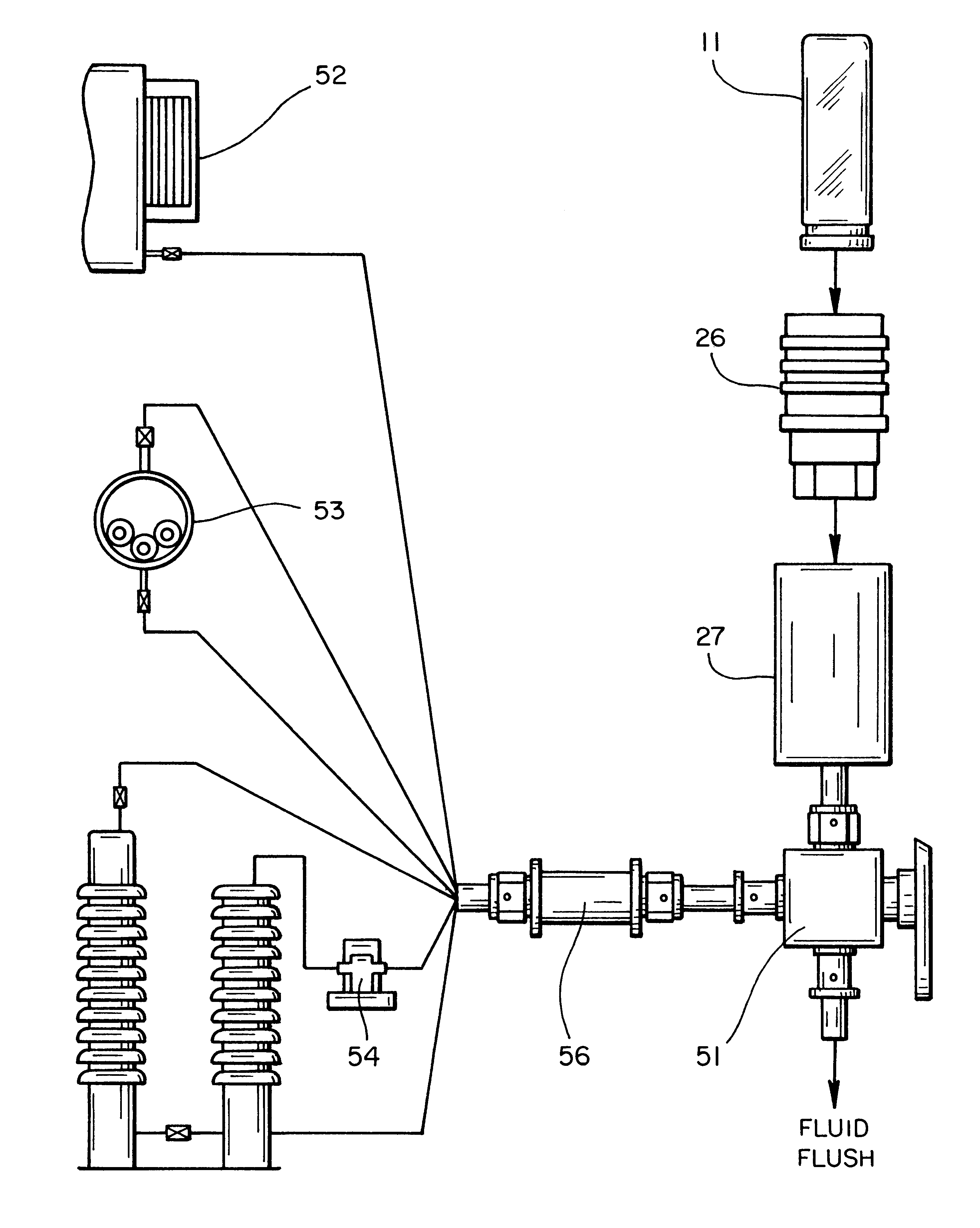
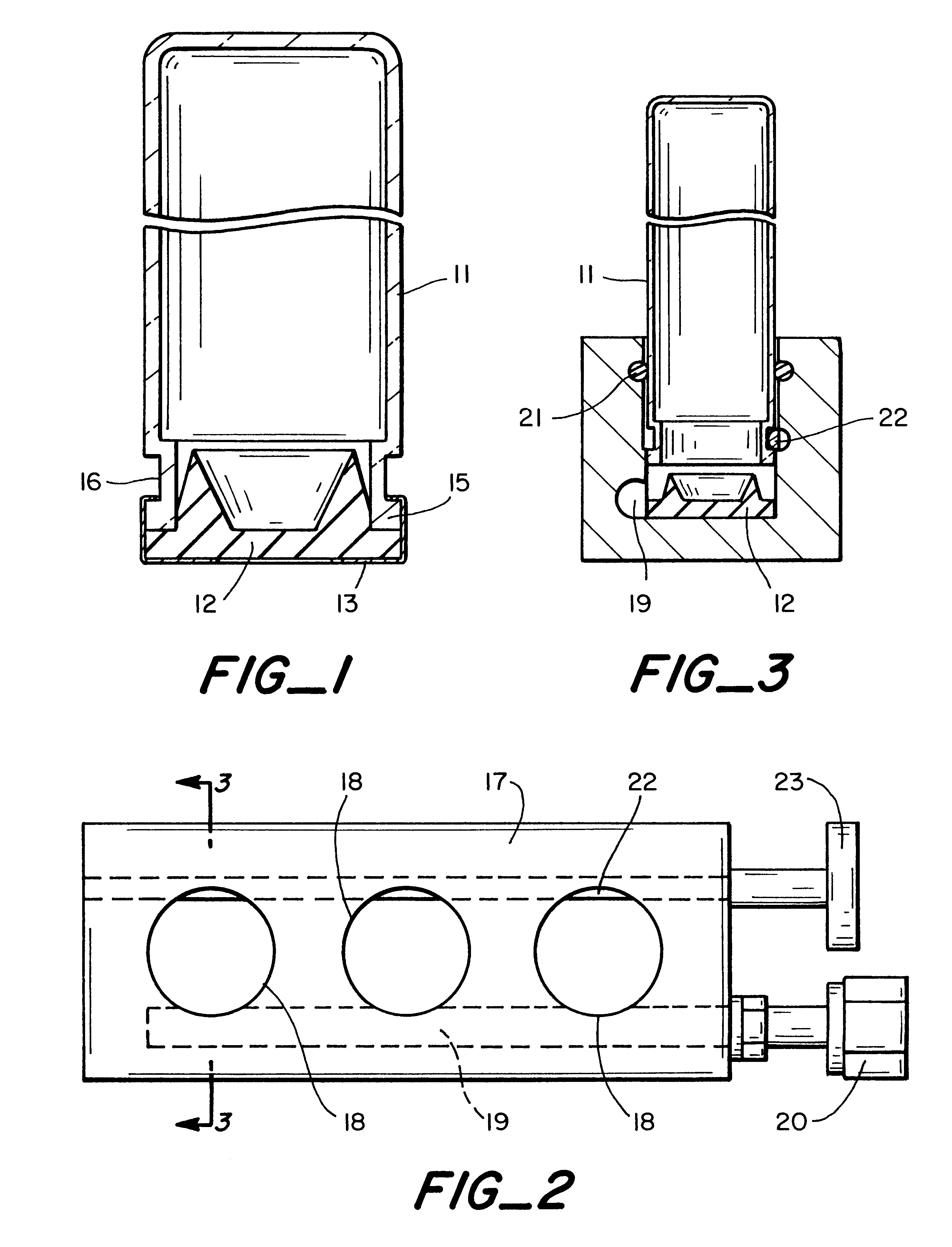
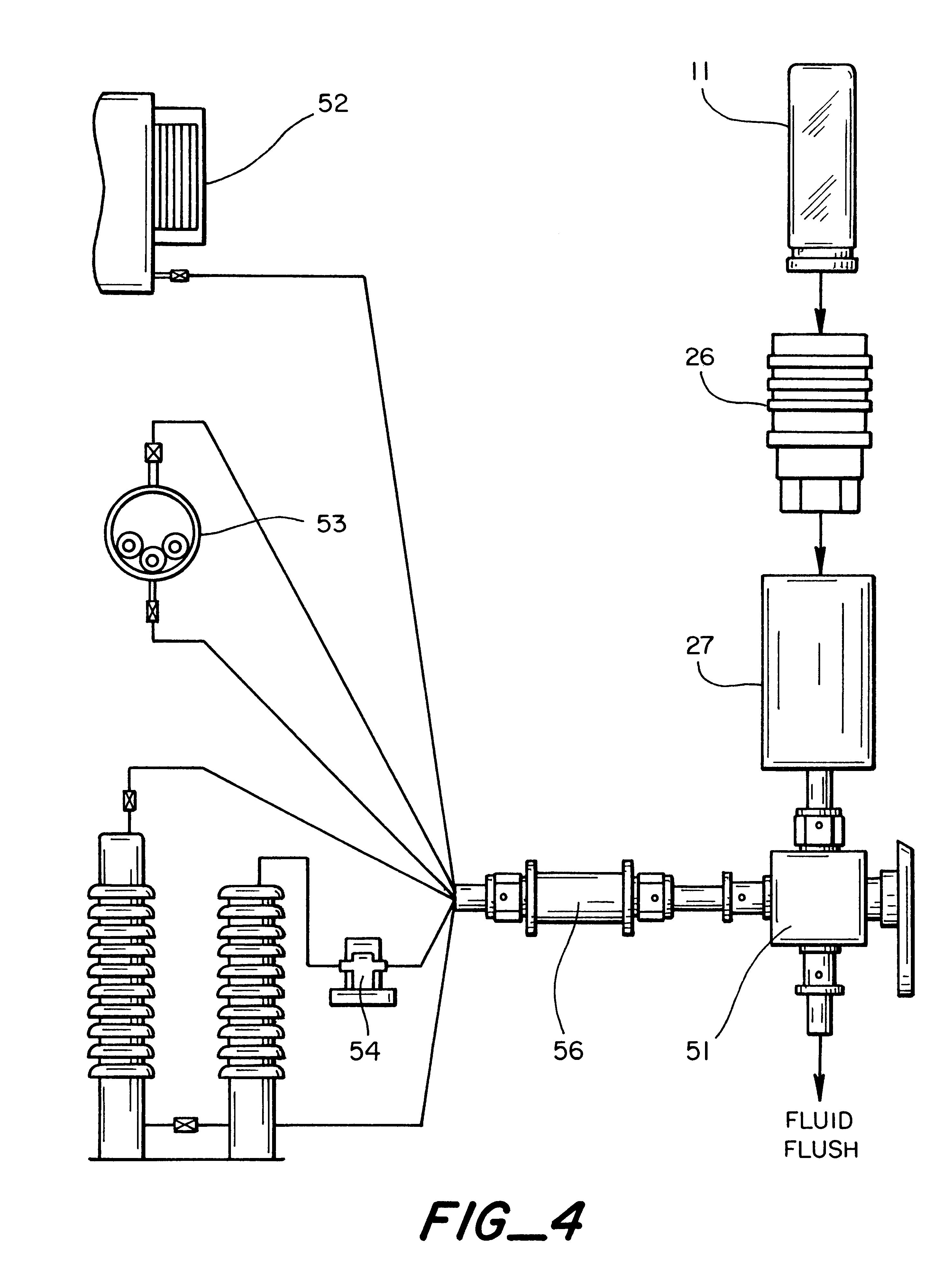
Referring to FIG. 1, a transparent evacuated disposable 20 ml crimp-top headspace vial 11 is sealed with a rubber stopper 12, inserted into the open end, and held by a crimp cap 13 which extends over the stopper and over the edge of the rim 15 into the neck 16. The stopper material should have low gas permeability, good resilience, and compatibility with hydrocarbon fluids. The most important characteristic is low gas permeability which determines the time the vial can maintain a proper vacuum. The vacuum assures that a minimal concentration of oxygen and nitrogen are in the vial prior to introducing a sample. After sampling, the stopper must contain the gases from the fluid until an analysis of the gases is performed. The stopper material needs to enable the penetration of a hollow needle through which the sample fluid can be introduced into the evacuated vial and which is self-healing or -sealing when the sampling needle is removed.

The time lag for gas diffusion through a rubbery ...


PUM

PropertyMeasurementUnit
thicknessesaaaaaaaaaa
gas permeabilityaaaaaaaaaa
compressive forceaaaaaaaaaa

Abstract

A system and method for field fluid sampling and analyzing dissolved gases in electrical equipment fluids is described. The system includes a disposable vial which is sealed with a self-sealing stopper. Fluid to be analyzed is inserted into the vial by a hollow needle. Also described is apparatus for evacuating and sealing the vial and apparatus for introducing fluid from electrical equipment into the vial.

Description

The present invention relates generally to a method and apparatus for field fluid sampling and dissolved gas analysis utilizing an evacuated disposable sampling vial, and to ancillary apparatus for vial evacuation and field fluid sampling.Fluid-filled equipment, which includes transformers, cables, bushings, terminations and circuit breakers, is an integral part of the electrical system. This diverse equipment represents considerable utility investment and a high proportion of it is advancing in age. About 30% of the high pressure fluid-filled transmission cable systems, the predominant form of U.S. underground transmission, are over 25 years old. Likewise, about 35% of the power transformers are over 30 years old. The rapidly emerging utility business climate dictates efficient use of such assets. Among other measures, this dictates proper periodic maintenance. The assessment of the condition of fluid-filled equipment through traditional evaluations of a fluid sample (dielectric br...

Claims


Application Information

Patent Timeline
Patent Type & Authority Patents(United States)
IPC IPC(8): G01N1/10G01N1/34G01N1/20
CPCG01N1/10G01N2001/1037G01N2001/2078G01N2001/4066
Inventor MOREL, OSCAR E.SINGH, NIRMALMCDONNELL, GERALD E.
Owner ELECTRIC POWER RES INST INC
Learn More