Method and device for dissolved gas analysis

a technology of dissolved gas and analysis method, which is applied in the direction of optical radiation measurement, instruments, and sensing radiation from gases/flames, etc., can solve the problems of personnel injury, expensive equipment replacement, and high cost of failure,

Active Publication Date: 2014-02-06
GENERAL ELECTRIC CO
View PDF17 Cites 10 Cited by
  • Summary
  • Abstract
  • Description
  • Claims
  • Application Information

AI Technical Summary

Problems solved by technology

Often electrical distribution equipment is used in a mission critical environment in which failure can be very expensive or even catastrophic because of a loss of electric power to critical systems.
Also, failure of electrical distribution equipment ordinarily results in a great deal of damage to the equipment itself and surrounding equipment thus requiring replacement of expensive equipment.
Further, such failure can cause injury to personnel due electric shock, fire, or explosion.
However, these methods suffer from inaccuracy, uncertainties and repeatability issues generally involved with the complicated extraction process.
The calculations have several assumptions involved, leading to errors and uncertainties.

Method used


Image

  • Method and device for dissolved gas analysis
  • Method and device for dissolved gas analysis
  • Method and device for dissolved gas analysis

Examples


example 1

[0058]The following example demonstrates a change in temperature of a fluid on absorption of radiation of a wavelength.

[0059]Two samples, a water sample and a transformer oil sample were taken in small amounts (about 300 microliters) in individual containers. Both samples did not contain any gas. The samples were irradiated individually with radiation of wavelengths about 1942 nm and about 1947 nm, respectively, by using a quantum cascade laser (QCL). Each sample was measured for a change in temperature through a resistive temperature sensor (Pt100). FIGS. 4 and 5 are graphs showing the changes in temperatures of the water sample and the oil sample as a function of time during a period until the temperature of the samples reached a steady state temperature. The change in temperature (ΔTss) was measure about 170 millikelvin for the water sample, and about 1.2 millikelvin for the oil sample. The change in temperature for each of the samples confirms measurable absorption of the radiat...

example 2

[0061]The following example demonstrates initial calculations to estimate approximate temperature rise for a gas dissolved in the dielectric oil.

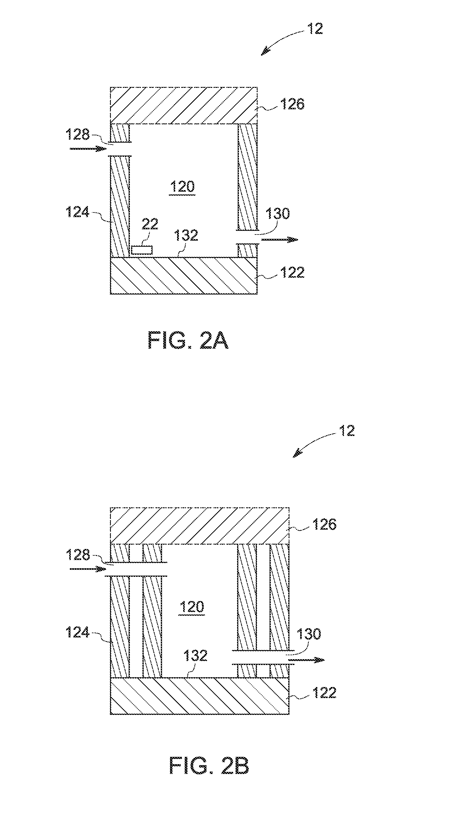
[0062]3 samples of transformer oil were considered for these calculations. Table 1 shows 3 samples, each containing a dissolved gas, the amount of the gas present in the sample, and the wavelength used to irradiate the sample. A fluid container as shown in FIG. 2A, made of quartz, having volume space length of 5 millimeters and diameter of 3 millimeters was considered to be filled with a sample. For calculations, the wall thicknesses of the container were not considered, and heat losses from the container were lumped into a thermal resistance of about 700 k / W. The expected temperature change for different gases and for different gas concentrations were calculated per formula (ii) given above, and are shown in the graphs of FIGS. 6, 7, and 8.

TABLE 1SampleGas dissolvedWavelength (cm−1)Sample 1CO23300Sample 2C2H22127Sample 3CO2314


PUM


Abstract

A method for dissolved gas analysis is presented. The method includes the steps of irradiating a fluid with electromagnetic radiation; and determining a concentration of a gas as a function of a temperature change of the fluid in response to the irradiation. A device for such an analysis of dissolved gases in a fluid, and a system having such device are also described.

Description

BACKGROUND OF THE INVENTION[0001]1. Technical Field[0002]The subject matter disclosed generally relates to measuring and testing of dissolved gases, and more specifically to a method and apparatus for selectively detecting and monitoring dissolved gases in a fluid, such as transformer oil.[0003]2. Related Art[0004]Electrical equipment, particularly medium-voltage or high-voltage electrical distribution equipment, requires a high degree of electrical and thermal insulation between components. Accordingly, it is well known to encapsulate components of electrical equipment, such as coils of a transformer, in a containment vessel and to fill the containment vessel with a fluid. The fluid facilitates dissipation of heat generated by the components and can be circulated through a heat exchanger to efficiently lower the operating temperature of the components. The fluid also serves as electrical insulation between components or to supplement other forms of insulation disposed around the co...

Claims


Application Information

Patent Timeline
Patent Type & Authority Applications(United States)
IPC IPC(8): G01J5/00
CPCG01J5/0014G01N21/3504G01N25/4873G01N21/359
Inventor MAITY, SANDIPKAVOORI SETHUMADHAVAN, NAGAPRIYASINHA, SHASHANK
Owner GENERAL ELECTRIC CO
Why Eureka
Try Eureka