
Exhaust pipe assembly for multi-cylinder internal combustion engine

Inactive Publication Date: 2001-03-27
YUTAKA GIKEN CO LTD +1
View PDF9 Cites 20 Cited by
  • Summary
  • Abstract
  • Description
  • Claims
  • Application Information

AI Technical Summary

Problems solved by technology

This kind of welding work is not easy to perform and is low in workability (or welding efficiency).
In addition, there is a disadvantage in that welding defects, if any, cannot be easily located and repaired.
As a result, the temperature difference between the V-shaped portions and the outer arched portions becomes so large as to cause cracks.
Therefore, the thickness T of the intermediate flange f becomes large and the heat is accumulated therein, with the result that the intermediate flange f is likely to be subject to a damage by the heat.
To minimize this kind of disadvantage, a thicker and highly heat-resistant material must be used, resulting in a lager weight.
Even if these holes are formed by cutting work, the intermediate flange f is likely to cause cracks at welding beads due to thermal strains by welding, if the distance 1 is minimized.

Method used


Image

  • Exhaust pipe assembly for multi-cylinder internal combustion engine
  • Exhaust pipe assembly for multi-cylinder internal combustion engine
  • Exhaust pipe assembly for multi-cylinder internal combustion engine

Examples


Embodiment Construction

A preferred embodiment of the present invention will now be explained with reference to the accompanying drawings.

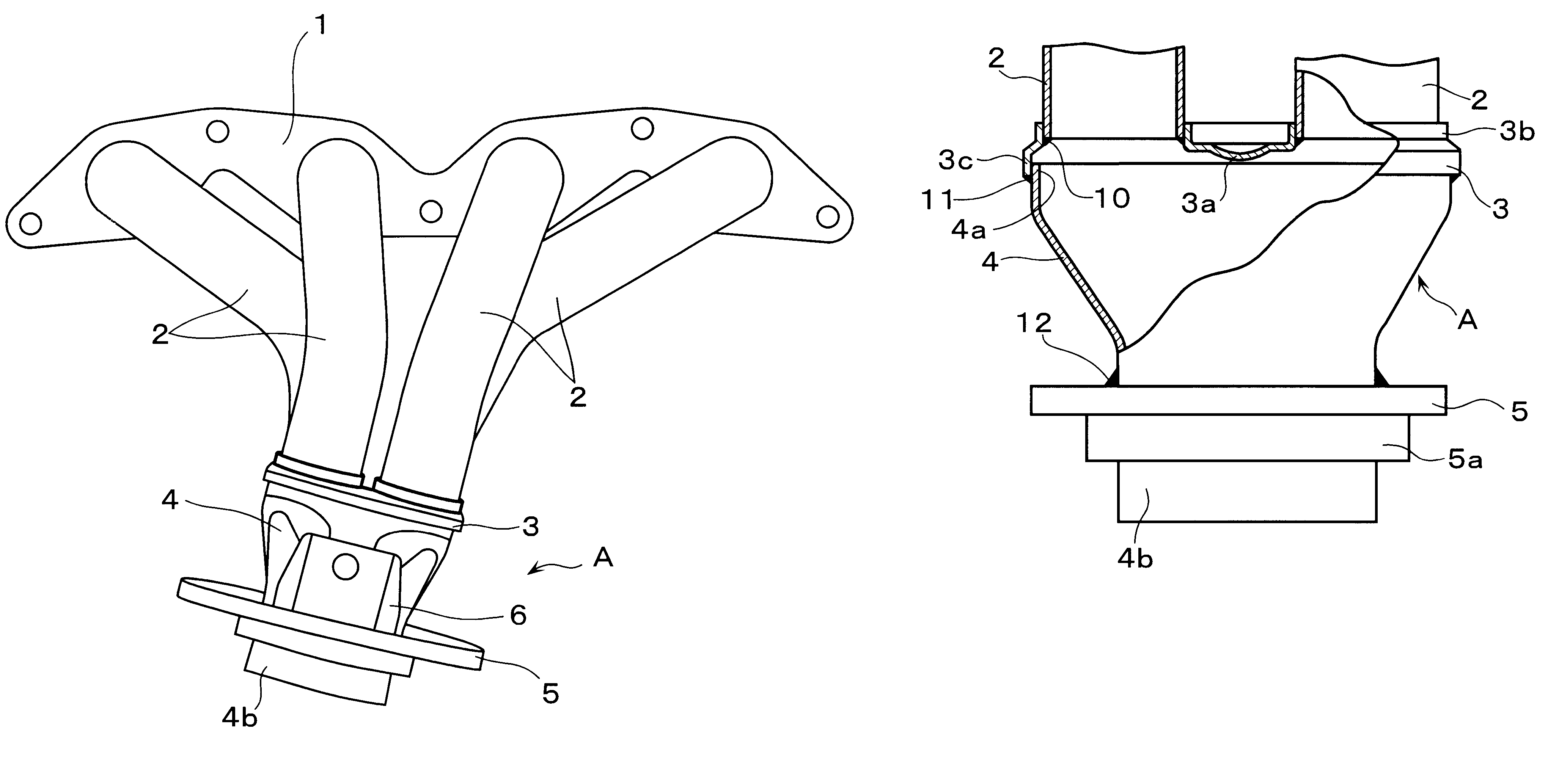
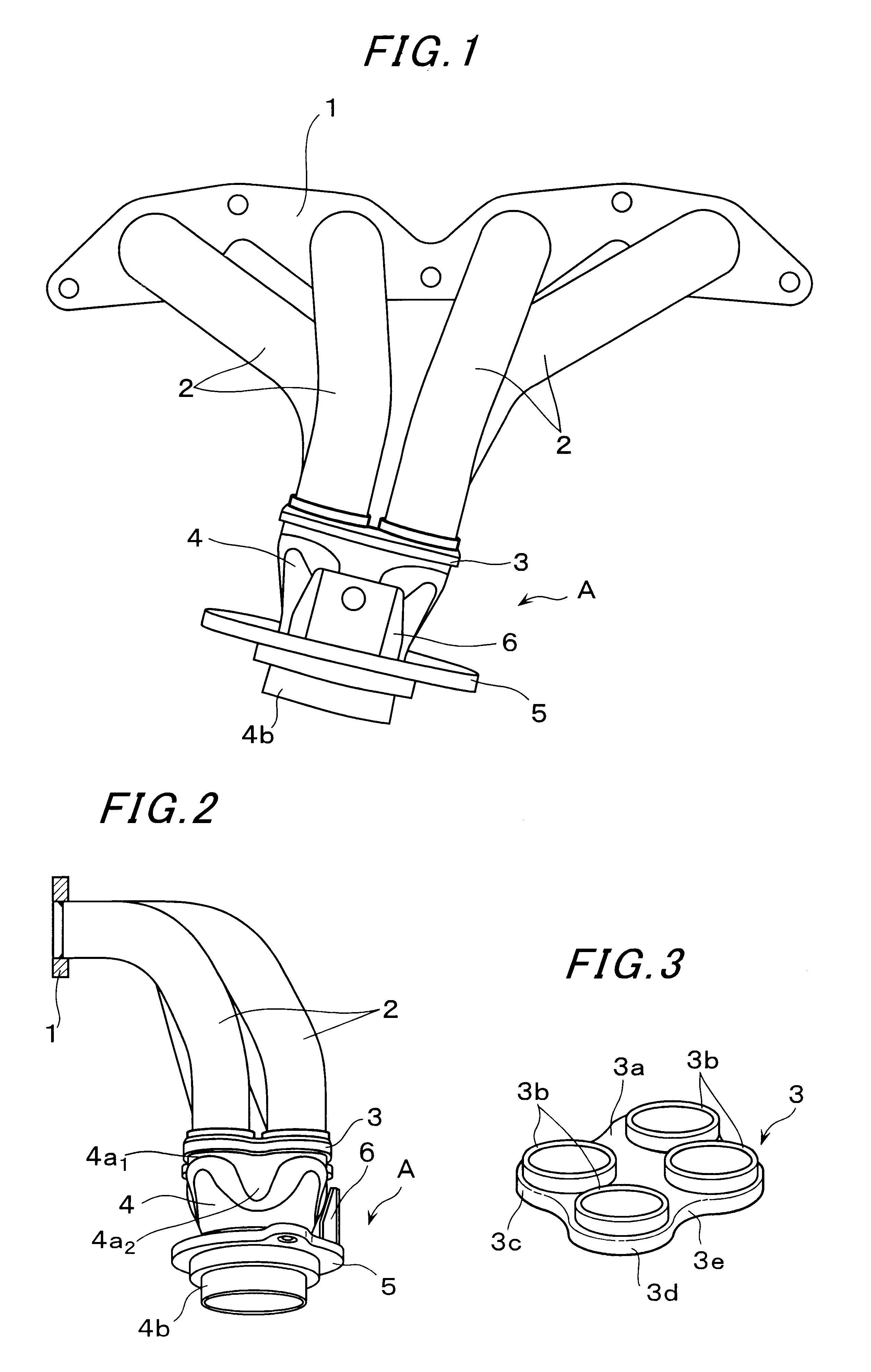
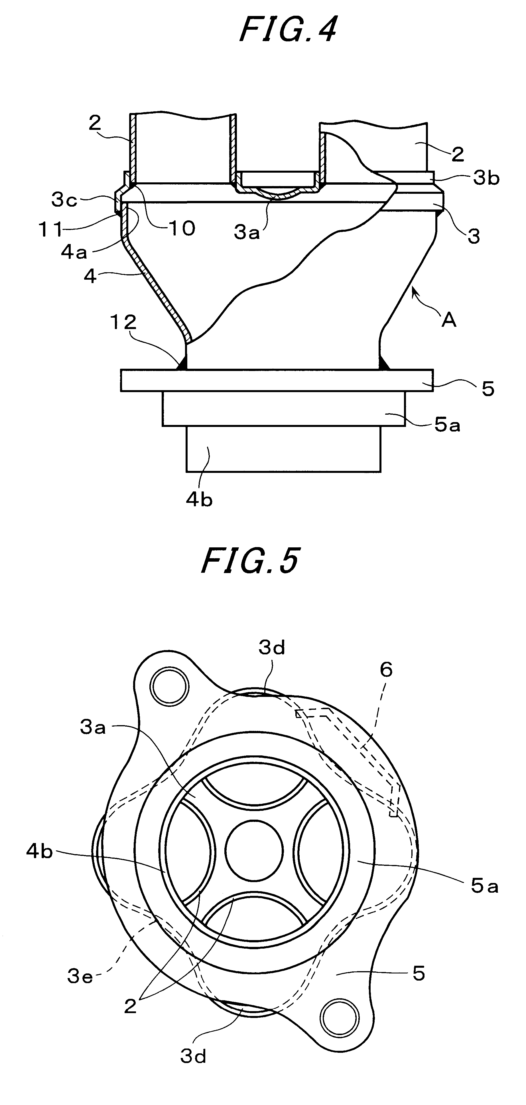
FIGS. 1 and 2 show an example of an exhaust pipe assembly in which the present invention is applied to a four-cylinder internal combustion engine. Reference numeral 1 denotes a flange which is provided on the side of a cylinder head. Reference numerals 2, 2, . . . denotes exhaust pipes which are manufactured by appropriately bending steel pipes. Reference numeral 3 denotes a coupling flange, reference numeral 4 denotes a collecting case, and reference numeral 5 denotes a flange on the downstream side of the exhaust gases. Reference numeral 6 denotes a fixing stay which is integrally provided on the flange 5.

The coupling flange 3 is manufactured by pressing a thin steel plate such that, as shown in FIG. 3, four burred portions 3b (i.e., portions projecting as a result of punching and bending work) are formed upward out of a main surface 3a independent of one another and a...


PUM


Abstract

An exhaust pipe assembly for a multi-cylinder internal combustion engine is made up of a plurality of exhaust pipes made of steel whose upstream ends are connected to a flange provided for connection to a cylinder head, a collecting case to which downstream ends of the exhaust pipes are connected, and a coupling flange interposed between the exhaust pipes and the collecting case. The coupling flange is made of a thin steel plate and has upward burred portions which are circular in shape and into which respective downstream ends of the exhaust pipes are separately inserted for welding with the burred portions, and a downward bent portion whose peripheral edge portion is fitted onto an upper outside end portion of the collecting case for welding with the bent portion.

Description

1. Field of the InventionThe present invention relates to an exhaust pipe assembly for a multi-cylinder internal combustion engine, in which exhaust pipes to be connected to a head of the engine are made of steel pipes.2. Description of the Related ArtThe structure of an exhaust pipe assembly in which steel pipes are used in making exhaust pipes is shown in, e.g., Japanese Published Unexamined Utility Model Registration Application No. 1819 / 1993, as illustrated in FIGS. 6A through 6C. In FIG. 6A, reference alphabet "a" denotes a flange which is connected to a cylinder head of an internal combustion engine, reference alphabets b denote exhaust pipes which are made of steel pipes, alphabet c denotes a collecting case (or an assembly casing), and alphabet d denotes a flange which is connected to an exhaust gas purifier. Downstream ends of the exhaust pipes b are shaped into sectors (or fan shapes) b.sub.1 as shown in FIG. 6B. The V-shaped portions (i.e., the portions formed by two radi...

Claims


Application Information

Patent Timeline
IPC IPC(8): F01N7/10F01N7/08F01N13/08F01N13/10
CPCF01N13/08F01N13/10F01N2450/22
Inventor AKABA, MANABUFURUHASHI, KAZUHIROMATSUZAWA, HIDEO
Owner YUTAKA GIKEN CO LTD
Features
  • Generate Ideas
  • Intellectual Property
  • Life Sciences
  • Materials
  • Tech Scout
  • Unparalleled Data Quality
  • Higher Quality Content
  • 60% Fewer Hallucinations
Learn More