
Flow control capsule for clutch lubrication and cooling

Inactive Publication Date: 2001-03-27
BORGWARNER INC
View PDF8 Cites 55 Cited by
  • Summary
  • Abstract
  • Description
  • Claims
  • Application Information

AI Technical Summary

Benefits of technology

Yet another feature of the present invention is to provide such an accumulator effect within the module by a second piston responsive to the piston actuation pressure and to compensate for variations in the piston actuation pressure.
The advantages of such an arrangement is that actuation pressure for the clutch pack can be separated from coolant flow in a multi-disc friction device such as multidisc clutch or brake packs thereby optimizing the control of friction device operations.

Problems solved by technology

If the frictional surfaces get too hot, they can burn which damages the friction surfaces, oxidizes the lubricant and degrades the clutch or brake operational effectiveness.
While the centrifugal forces are important to move the coolant between the engaging friction disks, because the perimeter of the plates is larger at the outer diameter than the inner diameter, the coolant tends to break up into droplets which reduces wetting of the friction surfaces and concomitantly reduces the cooling capacity of the fluid.
However, with conventional cooling schemes employed in the related art, unneeded coolant is often supplied to the open clutch or brake.
This condition reduces the efficiency of the transmission through viscous shear losses in the clutch or brake cooling fluid and ultimately results in lower fuel efficiency.
Additionally, when coolant is directed toward a friction device operating in an open pack mode wherein coolant is not needed, the coolant is not being used by friction devices, which are engaged or otherwise require cooling.
This also increases the volume of oil used by for a given transmission, differential or brake system and unnecessarily requires increasing the capacity of the associated pump.
However, in general, the systems that have been proposed in the related art suffer from the disadvantage that they are overly complex in operation or are too difficult to be manufactured in a cost-effective manner.

Method used


Image

  • Flow control capsule for clutch lubrication and cooling
  • Flow control capsule for clutch lubrication and cooling
  • Flow control capsule for clutch lubrication and cooling

Examples


Embodiment Construction

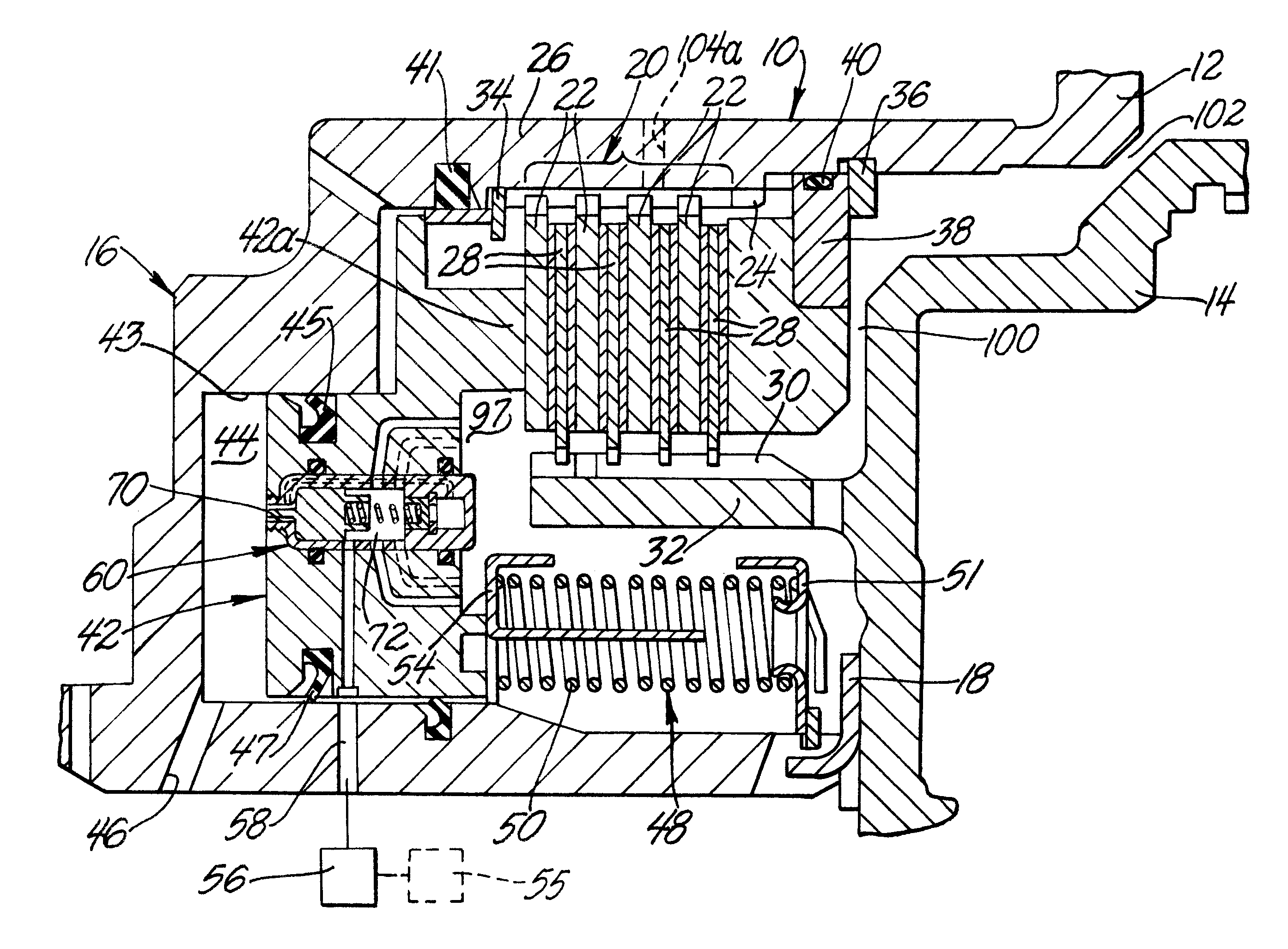
Referring now to FIG. 1, a multi-disc friction device such as a clutch or brake assembly of the present invention is generally indicated at 10. The friction device 10 is adapted to be employed in connection with a transmission, differential or brake system. For example only and not by way of limitation, as is commonly known in the art, but not shown in these figures, transmission assemblies typically include an input shaft which is operatively coupled to a prime mover, such as an internal combustion engine. In an automotive application, the transmission assembly also includes an output shaft, which is operatively coupled to driven wheels through other drivetrain components such as a drive shaft and an axle having a differential. At least one, and often a plurality of, gear sets is operatively coupled between the input and output shafts. The transmission casing supports the input shaft, the output shaft and the gear sets of the transmission assembly.

Various components of the gear set...


PUM


Abstract

A friction device includes a clutch pack operable to connect and disconnect drive and driven members for transferring and interrupting torque therebetween. A piston is supported in the clutch housing and defines a first expandable chamber. The piston carries a control module responsive to pressure in the expandable chamber for controlling coolant flow through a dedicated coolant flow passage through the actuator piston that includes mist-forming outlets on the face of the actuator piston.

Description

FIELD THE INVENTIONThe present invention relates, generally, to friction devices such as clutch or brake assemblies for use in transmissions, differentials or brake systems. More specifically, the present invention relate to a multi-disk friction clutch or brake system having selectively actuated lubrication for cooling the friction device on demand.DESCRIPTION OF THE RELATED ARTMulti-disk friction devices are employed in a wide range of applications as clutches or brakes. For example, such friction devices are frequently used in landbased vehicles. Generally speaking, land vehicles require three basic components. These components include a power plant (such as an internal combustion engine), a powertrain and wheels. The powertrain's main component is typically referred to as the "transmission." Engine torque and speed are converted in the transmission in accordance with the tractive-power demand of the vehicle. Transmissions include one or more gear sets, which may include an inner...

Claims


Application Information

Patent Timeline
IPC IPC(8): F16D25/0638F16D25/06F16D25/00F16D25/12
CPCF16D25/0638F16D25/123
Inventor SCHNEIDER, KARL F.
Owner BORGWARNER INC
Features
  • Generate Ideas
  • Intellectual Property
  • Life Sciences
  • Materials
  • Tech Scout
  • Unparalleled Data Quality
  • Higher Quality Content
  • 60% Fewer Hallucinations
Learn More