Dry etching endpoint detection system

a detection system and endpoint technology, applied in the field of endpoint detection, can solve the problems of erroneous endpoint detection, noise included in intensity signals, noise occurring in outputted intensity signals,

Inactive Publication Date: 2001-03-27
RICOH KK
View PDF5 Cites 108 Cited by
  • Summary
  • Abstract
  • Description
  • Claims
  • Application Information

AI Technical Summary

Problems solved by technology

In this method, however, there have been found several shortcomings such as, for example, fluctuations with time in the light emission intensity which is extracted from a reaction etching chamber, thereby resulting in noises included in the intensity signals.
When the light emission to be extracted is passing through the material to be etched, emitted light is affected by interference depending on the wavelength of the light thereby resulting in noise occurring in the outputted intensity signals, which will be detailed hereinbelow.
When these changes exceed a predete

Method used


Image

  • Dry etching endpoint detection system
  • Dry etching endpoint detection system
  • Dry etching endpoint detection system

Examples


Embodiment Construction

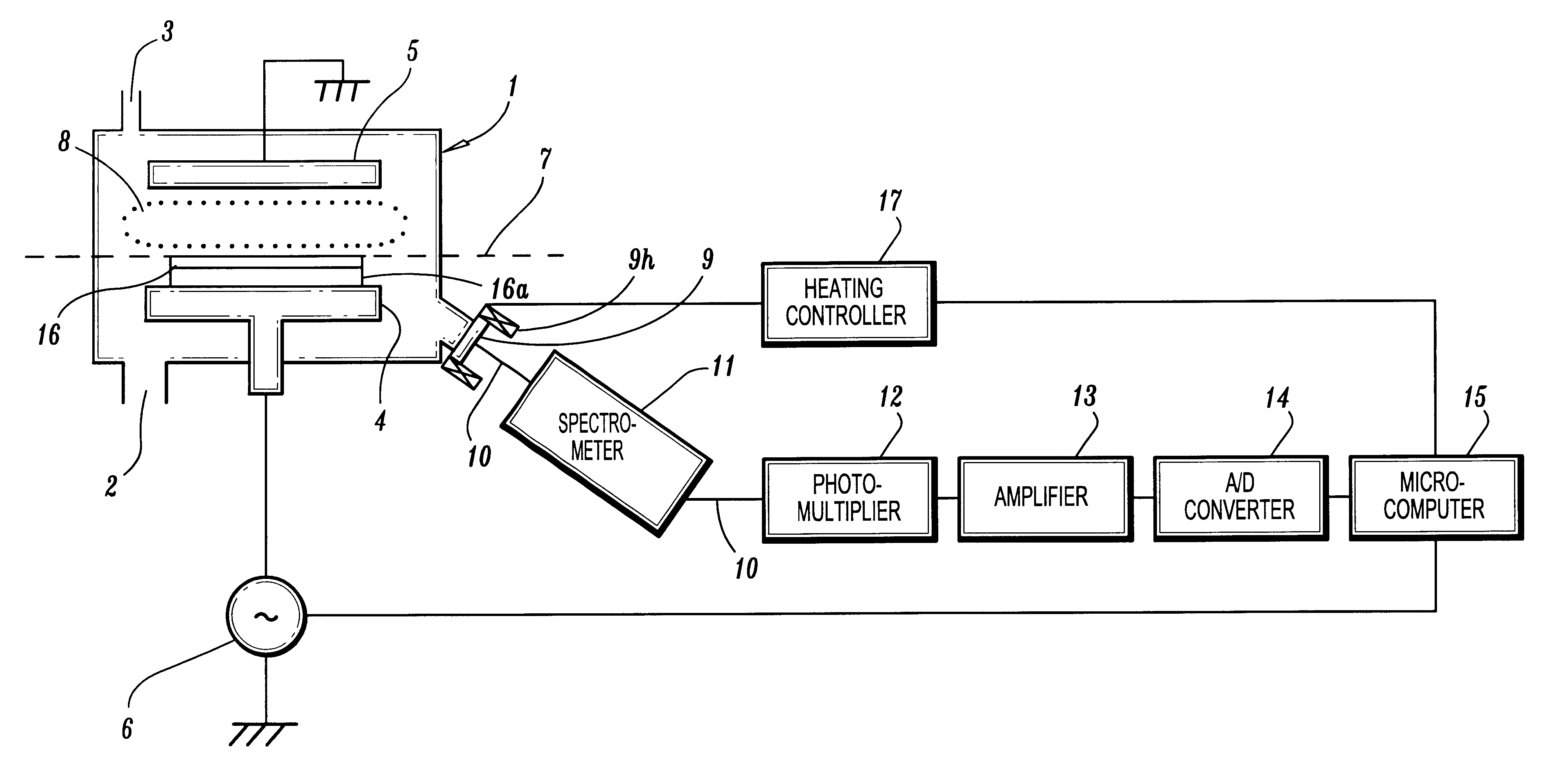
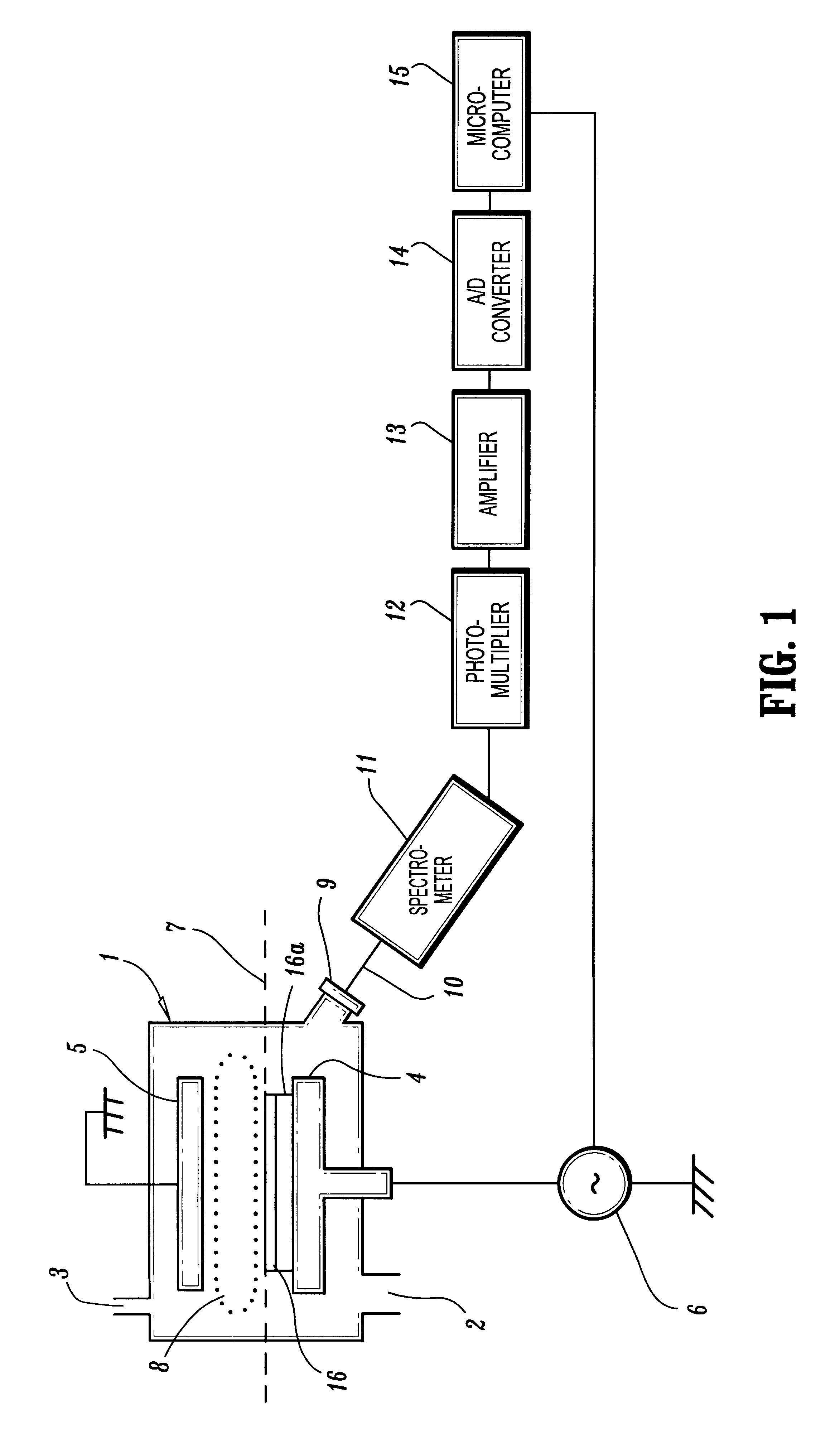
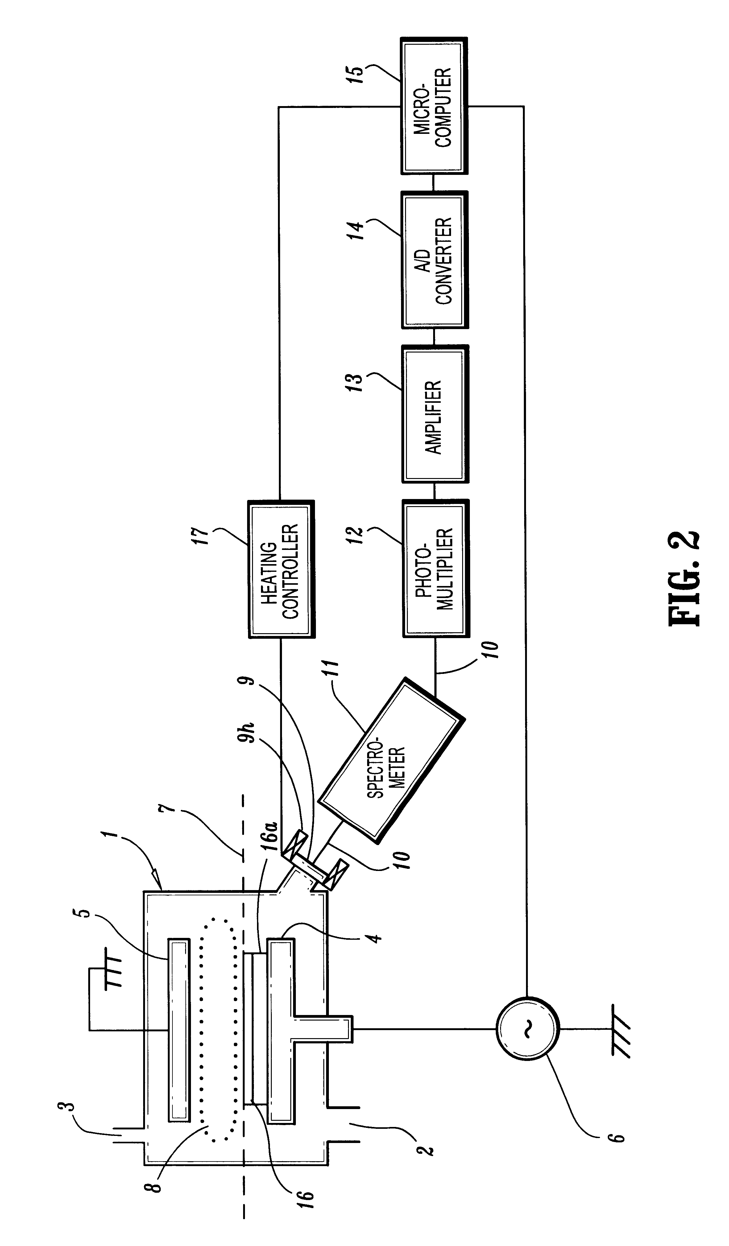
FIG. 1 is a schematic block diagram, illustrating major portions of a plasma etching system according to one embodiment disclosed herein.

Referring to FIG. 1, the etching system includes a reaction chamber 1, a body 16 (disposed on a substrate 16a)to be treated located therein, a suitable evacuating apparatus (not shown) attached thereto through a connection 2, and a gas feeding unit (not shown) also attached thereto through a connection 3 to supply gaseous materials for etch processing.

Also provided in the reaction chamber 1 are top and bottom electrodes 5 and 4, having broad faces. These broad faces of the electrodes are placed horizontally spaced apart to form a parallel plate reactor. The bottom electrode 4 is supplied with power, generally in the radio-frequency (RF) range, by a power source 6 and serves as a support for the body 16 (and the underlaying substrate 16a) to be treated. The top electrode 5 is maintained at ground potential.

Still further, the reaction chamber 1 inclu...


PUM

PropertyMeasurementUnit
Temperatureaaaaaaaaaa
Threshold limitaaaaaaaaaa

Abstract

A method and system for determining a dry etching endpoint, at which a dry etching process should be terminated. The dry etching process is carried out in a plasma etching system and comprises the steps of detecting an intensity of light emission generated in the dry etching process, the light emission being extracted through a window located on a side wall portion of a reaction chamber below a horizontal plane which is defined by a surface of a body to be etch treated. The detected intensity is compared to a predetermined threshold level.

Description

1. Field of the InventionThis invention relates to endpoint detection during dry etching processes such as plasma assisted discharge processing operations. More particularly, the present invention relates to a method and apparatus for such dry etching endpoint detection.2. Description of the Related ArtA number of etching methods have been utilized in semiconductor device fabrication processes, employing plasma discharges and charged particles produced by such discharges. These etching methods by plasma or dry etch methods have been used more and more widely in device fabrication.During device fabrication processes, a device portion to be etched typically comprises a layer of a first material disposed on top of a layer of a second different material, with certain portions of the first material exposed to plasma through a mask. The device portion is then subjected to plasma etching. The aim of the plasma etching process is to etch away portions of the first material until the second ...

Claims


Application Information

Patent Timeline
IPC IPC(8): G01N21/62G01N21/68H01J37/32C23F4/00H01L21/302H01L21/3065
CPCG01N21/68H01J37/32935H01J37/32963
Inventor KIJIMA, MASATO
Owner RICOH KK
Why Eureka
Try Eureka