Motion control systems using communication map to facilitating communication with motion control hardware
Inactive Publication Date: 2001-03-27
AUTOMATION MIDDLEWARE SOLUTIONS
View PDF5 Cites 53 Cited by
Summary
Abstract
Description
Claims
Application Information
AI Technical Summary
This helps you quickly interpret patents by identifying the three key elements:
Problems solved by technology
Method used
Benefits of technology
Benefits of technology
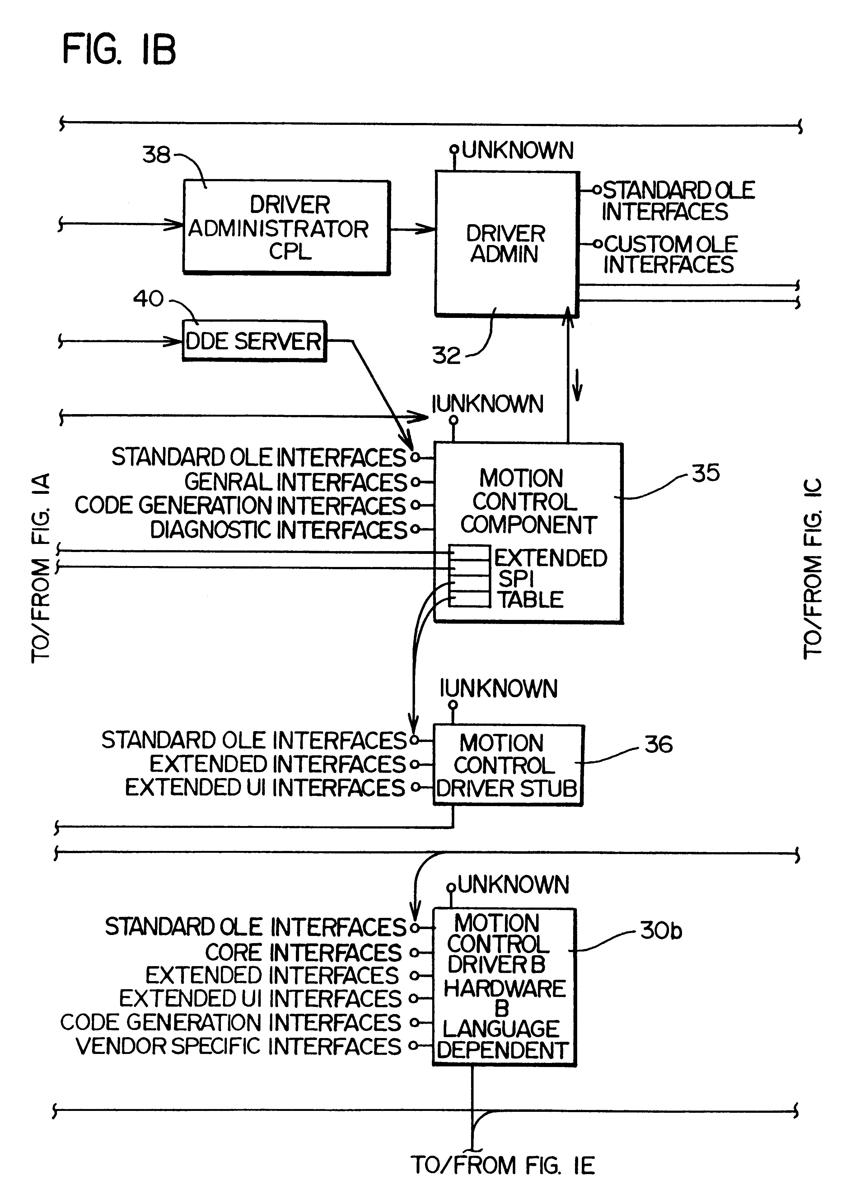
The driver stub module 36 is not required to implement the basic software model implemented by the system 22, but provides the system 22 with significantly greater flexibility to accommodate diverse motion control hardware configurations with minimal effort.
Similarly, the language driver 44 uses the response format template to parse a response data string sent by the particular motion control device 20 in response to the command data string. The response format template thus allows the language driver 44 to pass from the motion control device 20 to the motion control component 35 any commands and / or parameters necessary to enable the controlling application 26 to function as intended.
Problems solved by technology
While this approach does isolates the application programmer from the complexities of programming to each hardware configuration in existence, this approach does not provide the application programmer with the ability to control the hardware in base incremental steps.
The software driver model currently used for printers and the like is thus not applicable to the development of a sequence of control commands for motion control devices.
Method used
Image
Click on the blue label to locate the original text in one second.
Reading with bidirectional positioning of images and text.
Examples
example 2
The second example illustrates how the language driver 44 might deal with the Driver function IXMC_DrvExt_Test::SetVelocity.
Cmd Format: V%lf,+:@[snd]
Rsp Format: @[crlf]>@[rcv]
Driver function Call: pXMCDrvExtTest.fwdarw.SetVelocity(NOP, 22.0)
Explanation Set the velocity of the y axis to 22.0.
Raw Command String: "V,22.0:"
Raw Response String: ".backslash.r.backslash.n>"(expected)
example 3
The third example illustrates how the language driver 44 might deal with the Driver function IXMC_DrvExt_Test::GetVelocity.
Cmd Format: GV%b+:@[snd]
Rsp Format: %d,+@[crlf]@[rcv]
Driver function Call: pXMCDrvExtTest.fwdarw.GetVelocity(NOP, &dfY_Vel)
Explanation Get the velocity set for the y axis.
Raw Command String: "GVO1:"
Raw Response String: ",44.0.backslash.r.backslash.n>"(expected)
dfY_Vel=44.0
example 4
The fourth example illustrates how the language driver 44 might deal with the Driver function IXMC_DrvExt_Test::Reset.
Driver function Call: pXMCDrvExtTest.fwdarw.Reset( )
Explanation Reset the hardware.
Raw Command String1: "!RESET:"
Raw Response String1: ".backslash.r.backslash.n*VENDOR NAME-MODEL" (expected)
Raw Command String2: "MAO:MCO:LHO:"
Raw Response String2: ".backslash.r.backslash.n>"(expected)
While the language driver 44 is of particular importance in the context of the software system 22 described above, this technology may have broader application to any hardware in which ASCII strings are employed to transmit commands to and receive responses from hardware.
The language driver 44 will now be described in more detail. The language driver 44 is used by both the driver administration 32 and the motion control component 35. Its main purpose is to implement functionality that gener...
PUM
Abstract
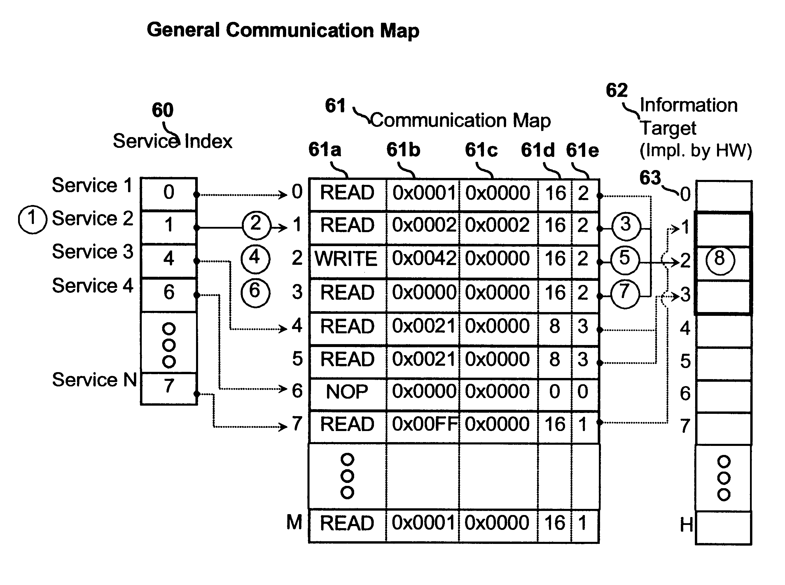
A system and method for facilitating communication between an application program and underlying motion control hardware in a hardware independent manner. A communication map maps a generic grid of mapping information cells to the actual information cells implemented by the particular hardware. Each actual information cell may be located in different areas and may transfer different values on each hardware platform. The communication map allows common functions to be used across a plurality of supported hardware device implementations.
Description
The present invention relates to motion control systems and, more particularly, to interface software that facilitates the creation of hardware independent motioncontrol software.The purpose of a motion control device is to move an object in a desired manner. The basic components of a motion control device are a controller and a mechanical system. The mechanical system translates signals generated by the controller into movement of an object.While the mechanical system commonly comprises a drive and an electrical motor, a number of other systems, such as hydraulic or vibrational systems, can be used to cause movement of an object based on a control signal.Additionally, it is possible for a motion control device to comprise a plurality of drives and motors to allow multi-axis control of the movement of the object.The present invention is of particular importance in the context of a mechanical system including at least one drive and electrical motor having a rotating shaft connected ...
Claims
Application Information
Patent Timeline
Application Date:The date an application was filed.
Publication Date:The date a patent or application was officially published.
First Publication Date:The earliest publication date of a patent with the same application number.
Issue Date:Publication date of the patent grant document.
PCT Entry Date:The Entry date of PCT National Phase.
Estimated Expiry Date:The statutory expiry date of a patent right according to the Patent Law, and it is the longest term of protection that the patent right can achieve without the termination of the patent right due to other reasons(Term extension factor has been taken into account ).
Invalid Date:Actual expiry date is based on effective date or publication date of legal transaction data of invalid patent.

