
Air handling controller for HVAC system for electric vehicles

a technology of air handling controller and electric vehicle, which is applied in the direction of electric energy management, electric devices, operating modes, etc., can solve the problems of less than optimal vehicle performance, unconditioned air exiting the inlet, and reducing passenger comfort, so as to improve vehicle performance, enhance passenger comfort, and reduce heat load

Inactive Publication Date: 2001-04-03
FCA US
View PDF3 Cites 58 Cited by
  • Summary
  • Abstract
  • Description
  • Claims
  • Application Information

AI Technical Summary

Benefits of technology

Automotive heating ventilation and air conditioning, HVAC, systems have traditionally been single loop designs in which the full volume of refrigerant flows through each component in the system. In an HVAC system, refrigerant in the vapor phase is pressurized by a compressor or pump. The pressurized refrigerant flows through a condenser which is typically configured as a long serpentine coil. As refrigerant flows through the condenser heat energy stored in the refrigerant is radiated to the external environment resulting in the refrigerant transitioning to a liquid phase. The liquefied refrigerant flows from the condenser to an expansion valve located prior to an evaporator. As the liquid flows through the expansion valve it is converted from a high pressure, high temperature liquid to a low pressure, low temperature spray allowing it to absorb heat. The refrigerant flows through the evaporator absorbing heat from the air that is blown through the evaporator fins. When a sufficient amount of heat is absorbed the refrigerant transitions to the vapor phase. Any further heat that is absorbed raises the vaporized refrigerant into the superheated temperature range where the temperature of the refrigerant increases beyond the saturation temperature. The superheated refrigerant flows from the outlet of the evaporator to the compressor where the cycle repeats. Generally, the refrigerant flowing into the compressor should be in the vapor phase to maximize pumping efficiency. The operation of the refrigerant loop in conventional automotive HVAC systems is controlled by cycling the compressor on and off, and by varying the volume of refrigerant that is permitted to flow through the expansion valve. Increasing the volume of refrigerant that flows through the valve lengthens the distance traversed by the liquid before it changes to the vapor phase, allowing the heat exchanger to operate at maximum efficiency.
One object of the present invention is to provide a system for selectively overriding the passenger air mixture selection to enhance passenger comfort.
Another object of the present invention is to improve vehicle performance by automatically adjusting the air mixture during predetermined vehicle operating modes.
A further object of the present invention is to reduce the heat load on the HVAC system.
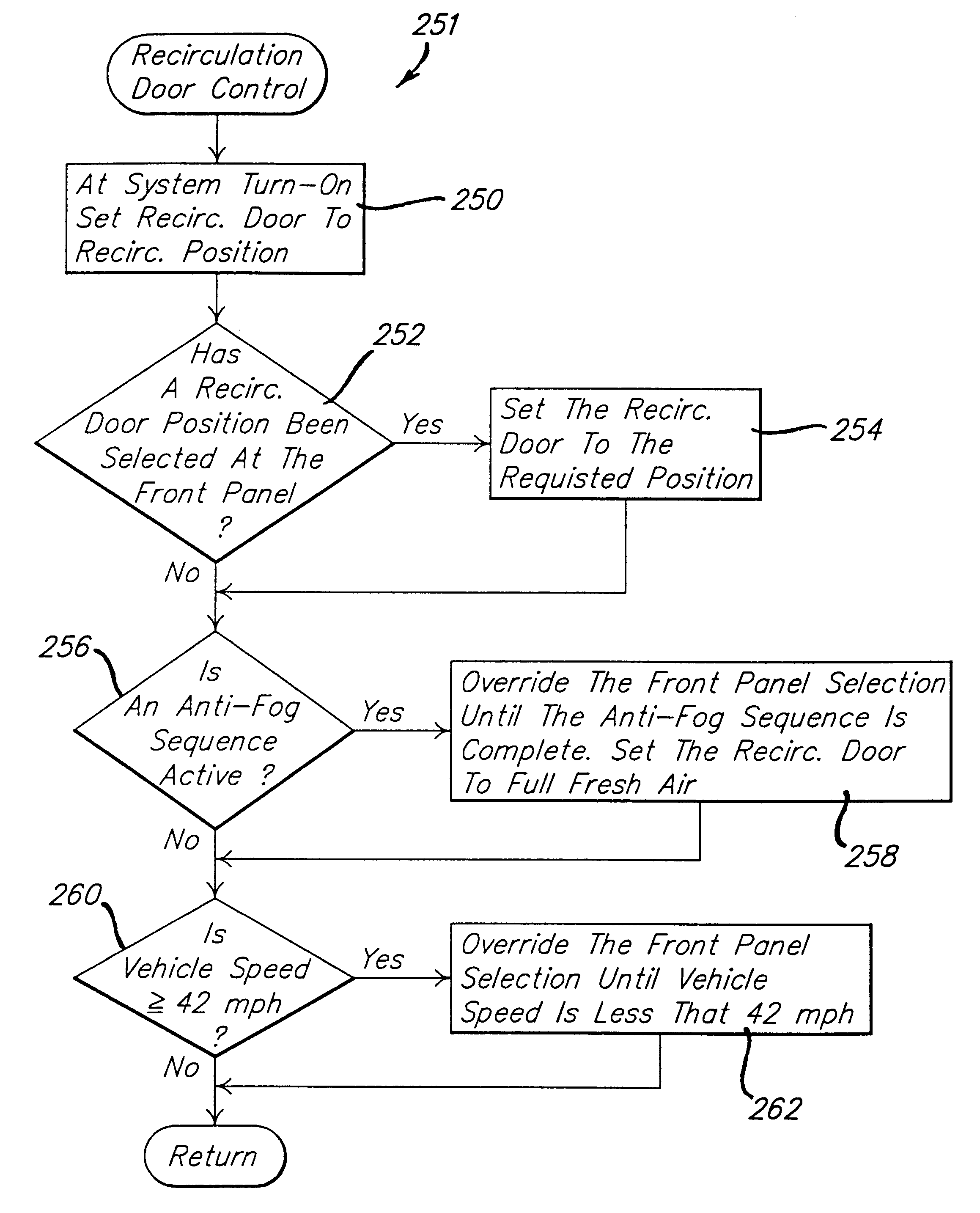
Accordingly, the invention provides an air-flow management system for controlling the supply air to a motor vehicle passenger compartment. The air-flow management system includes a reversible heat pump system for transferring heat energy between an outside environment and a refrigerant. Air from the outside environment, fresh air, and from the passenger compartment, recirculated air, is forced through the air-flow structure by a blower resulting in the transfer of heat energy between the refrigerant and the passenger compartment. A recirculation door provides a means for controlling the mixture of fresh air to recirculated air that flows through the air-flow structure. The position of the recirculation door is selectable by a controller to prevent fogging during the transition from cooling mode to heating mode, minimize the energy expended conditioning the passenger compartment air, and prevent the backflow of unconditioned outside air from the fresh air duct into the recirculation duct.

Problems solved by technology

However, under some operating conditions it leads to reduced passenger comfort and less than optimal vehicle performance.
The air exiting the inlets is unconditioned, directly subjecting passengers to outside air.
Not providing automatic override of the air mixture setting can subject passengers to degraded operating conditions in which the solutions are not obvious to the passenger.

Method used


Image

  • Air handling controller for HVAC system for electric vehicles
  • Air handling controller for HVAC system for electric vehicles
  • Air handling controller for HVAC system for electric vehicles

Examples


Embodiment Construction

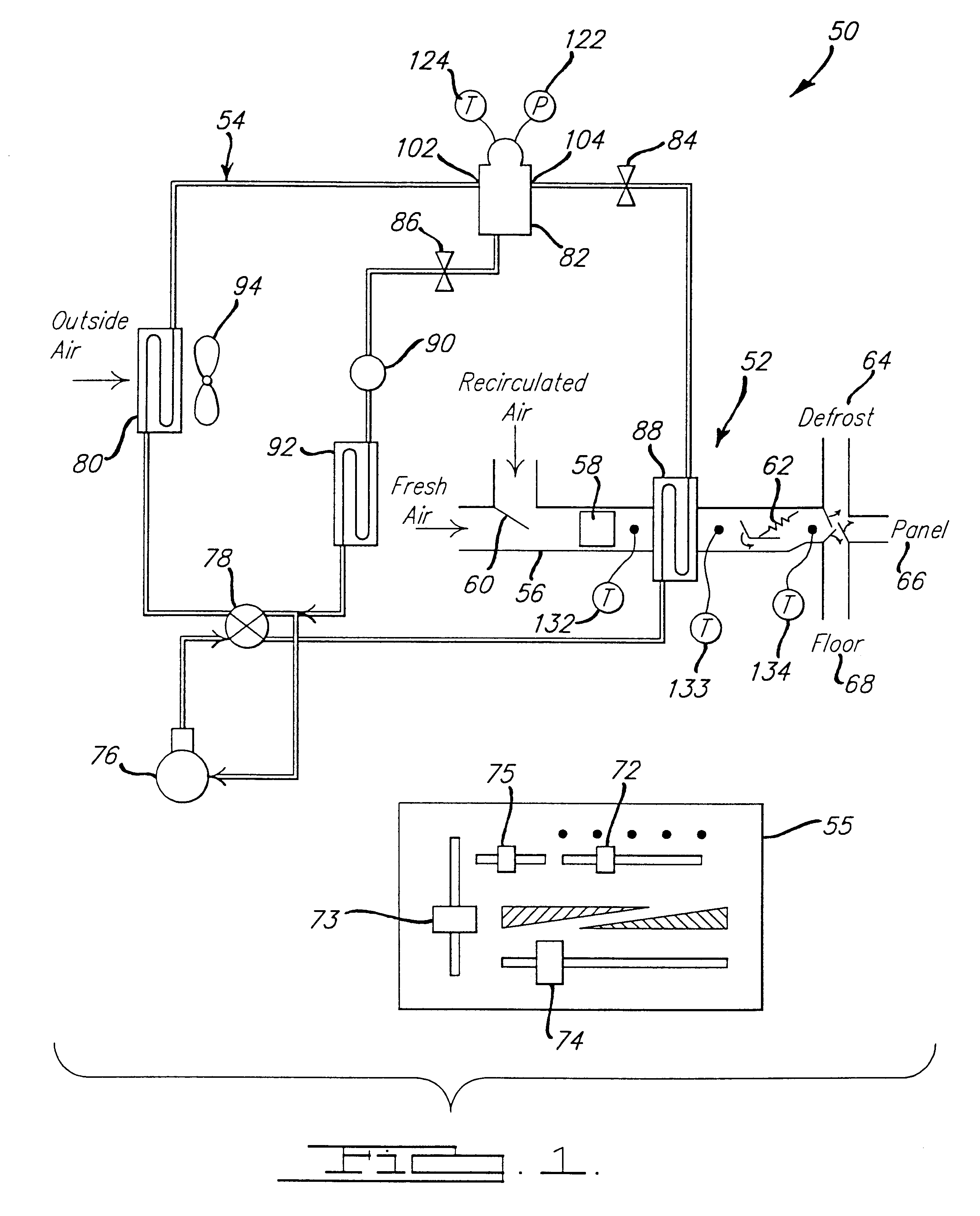
FIG. 1 illustrates an exemplary reversible HVAC system 50 for motor vehicles that includes an air-flow structure 52, a refrigerant flow system 54, and a front panel 55 for providing controlling inputs. The reversible HVAC system 50 can both heat and cool the passenger compartment air of a motor vehicle by using the refrigerant flow system 54 in conjunction with the air-flow structure 52 to transfer heat energy between the outside environment and the passenger compartment. In heating mode, heat energy is transferred from the outside environment to air that flows into the passenger compartment and in cooling mode, heat energy is transferred to the outside environment from air that flows into the passenger compartment. The refrigerant flow system 54 acts as a storage medium for heat energy that is being transferred between the outside environment and the passenger compartment. The air-flow structure 52 controls the flow of conditioned air into the passenger compartment. An inside heat ...


PUM


Abstract

An air-flow management system for controlling the supply air to a motor vehicle passenger compartment is disclosed. The air-flow management system includes a reversible heat pump system for transferring heat energy between an outside environment and a refrigerant. Air from the outside environment, fresh air, and from the passenger compartment, recirculated air, is forced through the air-flow structure by a blower resulting in the transfer of heat energy between the refrigerant and the passenger compartment. A recirculation door provides a means for controlling the mixture of fresh air to recirculated air that flows through the air-flow structure. The position of the recirculation door is selectable by a controller to prevent fogging during the transition from cooling mode to heating mode, minimize the energy expended conditioning the passenger compartment air, and prevent the backflow of unconditioned outside air from the fresh air duct into the recirculation duct.

Description

BACKGROUND AND SUMMARY OF THE INVENTIONThe present invention relates generally to automotive HVAC systems for controlling the environment of an automobile passenger compartment. More particularly, the invention relates to an air handling system for controlling the positioning of the fresh / recirc door in an automotive HVAC system.This application is related to co-pending applications titled Refrigerant Flow Management Center For Automobiles, Reversible Air Conditioning And Heat Pump HVAC System For Electric Vehicles, Controller For Reversible Air Conditioning And Heat Pump HVAC System For Electric Vehicles, Anti-Fog Controller For Reversible Air Conditioning And Heat Pump HVAC System For Electric Vehicles, Controller For Heating In Reversible Air Conditioning And Heat Pump HVAC System For Electric Vehicles, and System For Cooling Electric Vehicle Batteries. Each of these applications is incorporated by reference into the present application.Automotive heating ventilation and air cond...

Claims


Application Information

Patent Timeline
IPC IPC(8): B60H1/00B60H1/32
CPCB60H1/00278B60H1/00849B60H1/00907B60H1/3205B60H1/3208B60H1/3213B60L1/003B60L1/02B60L11/1803B60L3/003B60L11/1874B60H1/00392Y02T10/642B60H2001/00307B60H2001/00935B60H2001/3248B60H2001/3255B60H2001/3257B60H2001/326B60H2001/3263B60H2001/3264B60H2001/3266B60H2001/3272B60H2001/3277B60H2001/3282B60H2001/3285B60L2240/34B60L2240/36B60L2260/22B60L2270/44B60L2270/46B60L2240/12B60L2240/28B60L2240/421B60L2240/662B60L2240/80Y02T10/7005Y02T10/705Y02T90/16Y02T10/7291B60L50/51B60L58/26Y02T10/64Y02T10/70Y02T10/72
Inventor LAKE, BARRY J.TAGLIAPIETRA, LANCE C.TUCKFIELD, CHRISTOPHER A.
Owner FCA US
Learn More