Self-cooled oxygen-fuel burner for use in high-temperature and high-particulate furnaces

a self-cooled, oxygen-fuel burner technology, applied in the field of combustion, can solve the problems of increasing the frequency of maintenance, unable and the failure of the burner to meet the requirements of high-temperature and high-particulate furnaces

Inactive Publication Date: 2001-04-03
AIR LIQUIDE AMERICA INC +1
View PDF15 Cites 105 Cited by
  • Summary
  • Abstract
  • Description
  • Claims
  • Application Information

AI Technical Summary

Benefits of technology

The fuel velocity is preferably less than 150 ft / sec for the burner and method of the first and third aspects of the invention, and less than 50 ft / sec for the flat flame produced by the burner and method of the second and fourth aspects of the invention. The oxidant velocities are less than 300 ft / sec, depending on the axial-tangential swirl configuration.
The specific flow geometry for fuel and oxidant streams in the various aspects of the invention provide active cooling and sweeping of the burner block interior for cooler operation and avoiding particulate inspiration.
The self-cooled burner apparatus of the present invention are preferred for use with oxidants having oxygen concentration greater than that of air. The inventive burners and nozzles can fire in high-temperature (2200.degree. F. to 3000.degree. F.) and high-particulate (or high process volatiles / condensates) furnaces without over-heating or causing chemical corrosion damage to it's metallic burner nozzle and refractory burner block interior. Using various embodiments of nozzle and block shape, the burner can offer a traditional cylindrical flame or flat flame depending on the heating load requirements. The new features of this burner include unique fuel nozzle design for the streamline mixing of fuel and oxidant streams, a controlled swirl input to the oxidant flow for desired flame characteristics, a controlled expansion of flame envelope in the radial and axial dimensions, and efficient sweeping of burner block interior surface using oxidant to provide convective cooling and prevent any build up of process particulates. In addition, a relatively thick wall metallic nozzle construction with conduction fins enable efficient heat dissipation from the nozzle tip and providing a maintenance free burner operation.

Problems solved by technology

While such burners are useful for many purposes, there are disadvantages with such burners.
The major disadvantage of such burner blocks is that the flame shape, especially maximum flame diameter and / or flame length, is always dictated by the burner block L / D ratio and fuel and oxidant velocities.
The objective to design a tight burner block without any void becomes very difficult when burner firing rate (amount of fuel and oxidant flows) is varied over a wide range.
The consequence of plugged burner block can result in increased frequency of maintenance (in terms of cleaning burner and / or block or lower burner / block life) or a catastrophic failure (meltdown of block / burner) due to direct or indirect impingement / deflection of high temperature flame.
Another disadvantage of pipe-in-pipe shape burner block design is the difficulty in producing a flame which is expanded in a radial direction generally perpendicular to the direction of fuel and oxidant gas flows, referred to herein as a "flat" flame.
However, the same process is not yet proven using oxy-fuel burners.
The resulting flame is a "narrow" cylindrical flame based on exit diameter D. The pipe shape combustion chamber coupled with a narrow exit geometry does not provide sufficient room for the flame to expand in the radial direction or in the extreme situation a formation of flat flame.
The constant diameter geometry (pipe shape) negatively affects the maintenance of oxidant swirl due to wall friction.
If a swirling fluid stream is not allowed to expand in the radial direction, the intensity of swirl quickly dies due to wall friction effects.
The cooling of the burner block is also negatively affected due to the quick burnout of swirling oxidant in a relatively narrow diameter burner block.
Due to the fixed burner block geometry (cylindrical shape), flame characteristics such as the flame shape alteration in radial direction, cooling burner tips and block interior using oxidant flow, and cleaning burner block interior with sweeping oxidant stream are severely curtailed.

Method used


Image

  • Self-cooled oxygen-fuel burner for use in high-temperature and high-particulate furnaces
  • Self-cooled oxygen-fuel burner for use in high-temperature and high-particulate furnaces
  • Self-cooled oxygen-fuel burner for use in high-temperature and high-particulate furnaces

Examples


embodiment 2

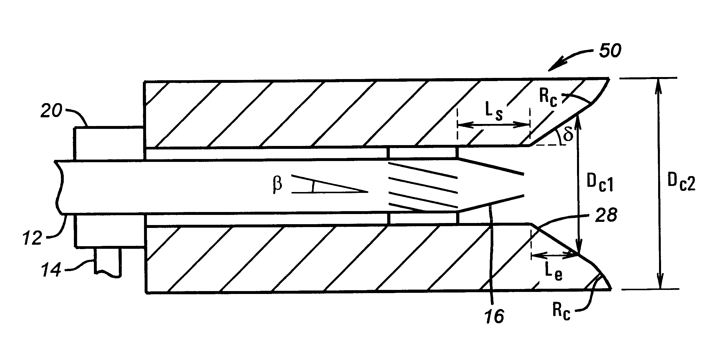
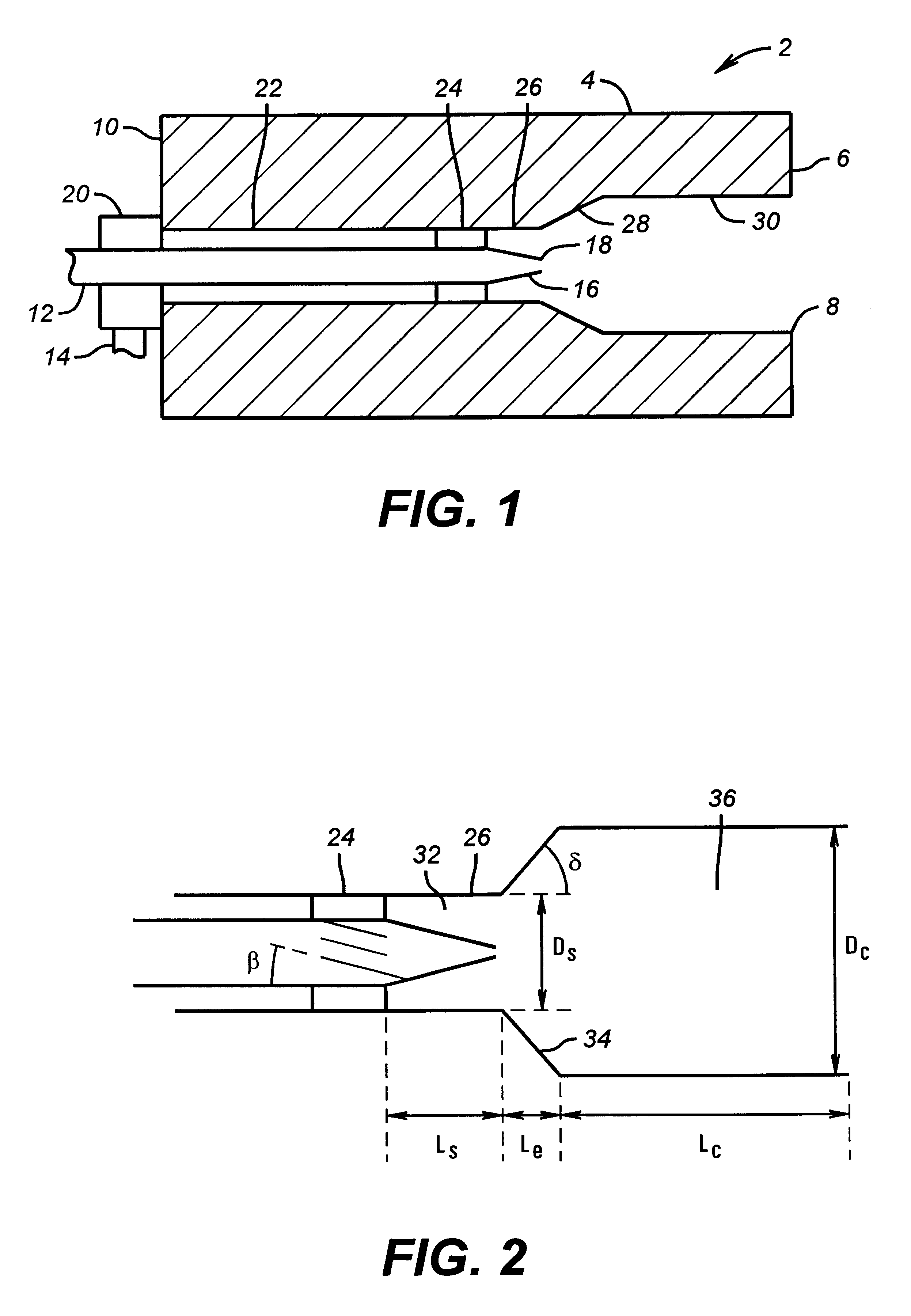
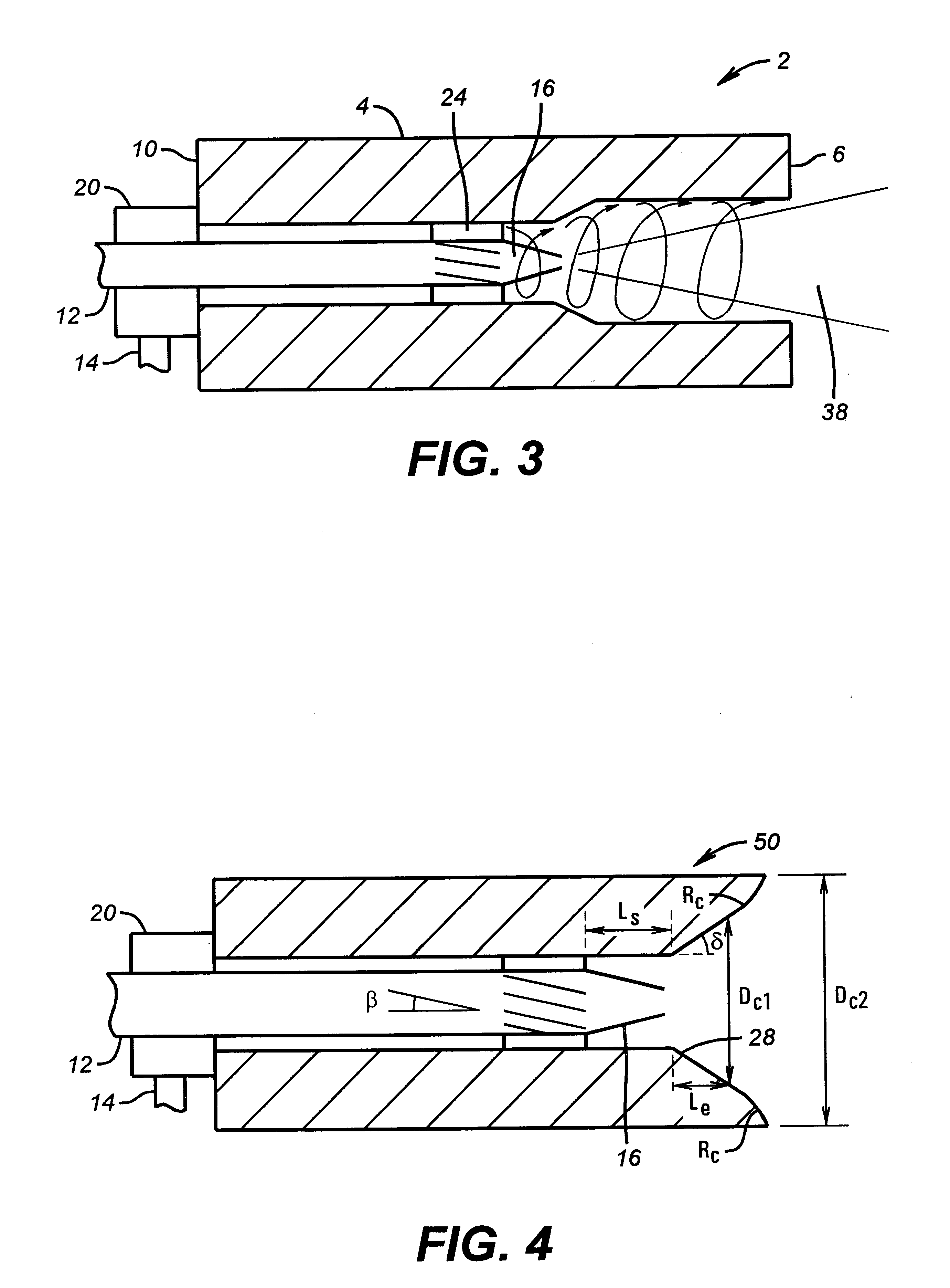
Referring to the figures, FIG. 1 illustrates in cross-section, side elevation view the first burner embodiment 2 in accordance with the invention. In this embodiment, the burner apparatus comprises a burner block 4, preferably refractory in nature, having an end or hot face 6, an exit 8 for flame and hot combustion gases, and a cold end 10. A fuel conduit 12 and an oxidant conduit 14 are fluidly connected to cold end 10 of burner block 4. Fuel conduit 12, preferably a metallic pipe, has a nozzle 16 attached thereto terminating in a nozzle tip 18. Oxidant conduit 14 feeds an oxidant plenum 20, which is fluidly connected to cold end 10, thus allowing oxidant to enter a substantially annular oxidant passage 22. The oxidant travels through oxidant conduit 14, plenum 20, and through substantially annular oxidant passage 22, which surrounds the fuel conduit 12, on its way toward one or more oxidant swirlers 24. Oxidant is thus given an radial-tangential flow component as it passes axially...

first embodiment

A numerical simulation of the burner described in the first embodiment has been performed, using the FLUENT / UNS computational fluid dynamics computer program. The domain used was a 2D axisymmetric field with swirl. The physical models employed include the PDF model for combustion, the RNG k-epsilon model for turbulence and the P1 model to account for the effects of radiative heat transfer. The natural gas flowrate considered was 2,300 scfh, and the oxygen flow rate was 4,900 scfh. The virtual walls of the combustion space were considered to be adiabatic, and conductive heat transfer through the block wall was taken into account. For comparison, two different cases have been investigated: the base case without swirl, and the second case including a swirl angle .beta. of 20.degree. for the oxygen flow only.

FIGS. 7a and 7b illustrate the oxygen profile in the two cases, FIG. 7a for the non-swirled flow, and FIG. 7b for the flow with swirl, for a burner constructed in accordance with FI...


PUM

PropertyMeasurementUnit
velocityaaaaaaaaaa
expansion angleaaaaaaaaaa
velocityaaaaaaaaaa

Abstract

A self-cooled oxidant-fuel burner consisting novel fuel and oxidant nozzles and three compartment refractory burner block design is proposed. The new oxidant-fuel burner can fire in high-temperature (2200° F. to 3000° F.) and high-particulate (or high process volatiles / condensates) furnaces without over-heating or causing chemical corrosion damage to it's metallic burner nozzle and refractory burner block interior. Using various embodiments of nozzle and block shape, the burner can offer a traditional cylindrical flame or flat flame depending on the heating load requirements. The new features of this burner include unique fuel nozzle design for the streamline mixing of fuel and oxidant streams, a controlled swirl input to the oxidant flow for desired flame characteristics, a controlled expansion of flame envelope in the radial and axial dimensions, and efficient sweeping of burner block interior surface using oxidant to provide convective cooling and prevent any build up of process particulates. In addition, a relatively thick wall metallic nozzle construction with heat conduction fins enable efficient heat dissipation from the nozzle tip and providing a maintenance free burner operation.

Description

1. Field of the InventionThis invention relates to combustion in general, and specifically to burners and methods of use of same to combust a fuel with an oxidant having an oxygen concentration greater than air.2. Prior ArtIn burner technology employing oxidants having oxygen concentration greater than the oxygen concentration in air, when such burners are used in glass manufacture, one object is to produce a luminous low temperature flame. Often these flames have low gas velocities and very simple (for example, pipe-in-pipe configuration) mixing strategy. Use of burner blocks having cylindrical combustion chambers is known, wherein the major process consists of a fuel-rich core surrounded by oxygen-rich sheath inside the cylindrical cavity. A cylindrical shape burner block (sometimes referred to as a precombustor) with a ratio of length "L" to diameter "D" of the cylindrical cavity between 2 and 6. In this L / D ratio range, the fuel and oxygen velocities (less than 600 ft / s) are cho...

Claims


Application Information

Patent Timeline
Patent Type & Authority Patents(United States)
IPC IPC(8): F23D14/00F23D14/24F23D14/32F23M5/00F23M5/02F23C3/00F23D14/22F23D14/48
CPCC03B5/2353F23D14/24F23D14/32F23M5/025C03B2211/60Y02E20/344Y02P40/50F23D14/00
Inventor JOSHI, MAHENDRA L.BORDERS, HARLEY A.MARIN, OVIDIUCHARON, OLIVIER
Owner AIR LIQUIDE AMERICA INC
Why Eureka
Try Eureka