
Method of and apparatuses for reducing infrared loading on display devices

Inactive Publication Date: 2001-04-03
HONEYWELL INC
View PDF26 Cites 78 Cited by
  • Summary
  • Abstract
  • Description
  • Claims
  • Application Information

AI Technical Summary

Benefits of technology

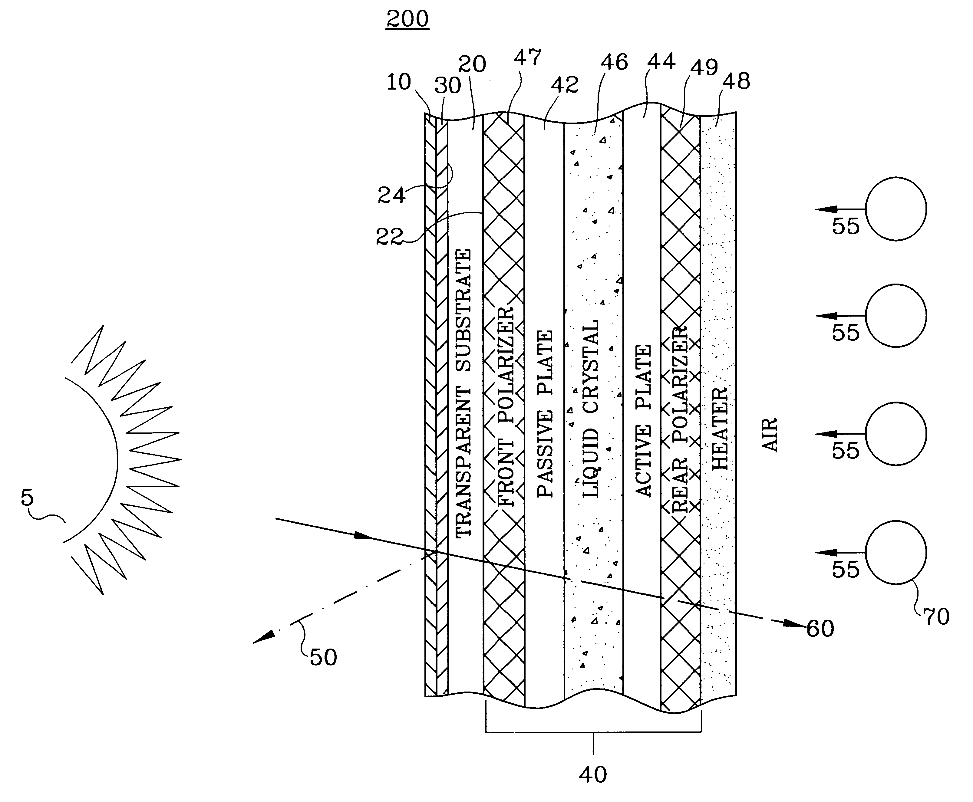
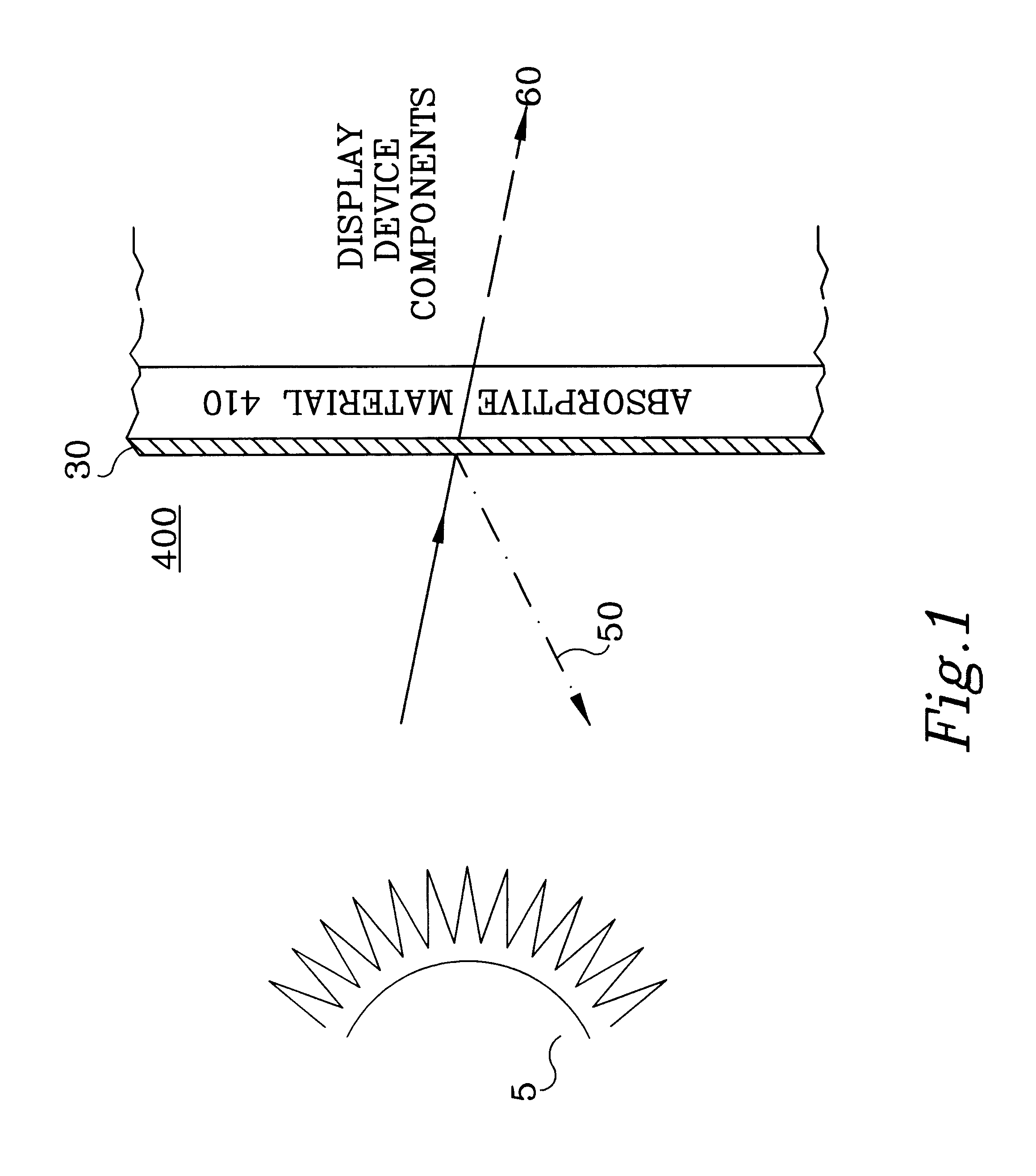
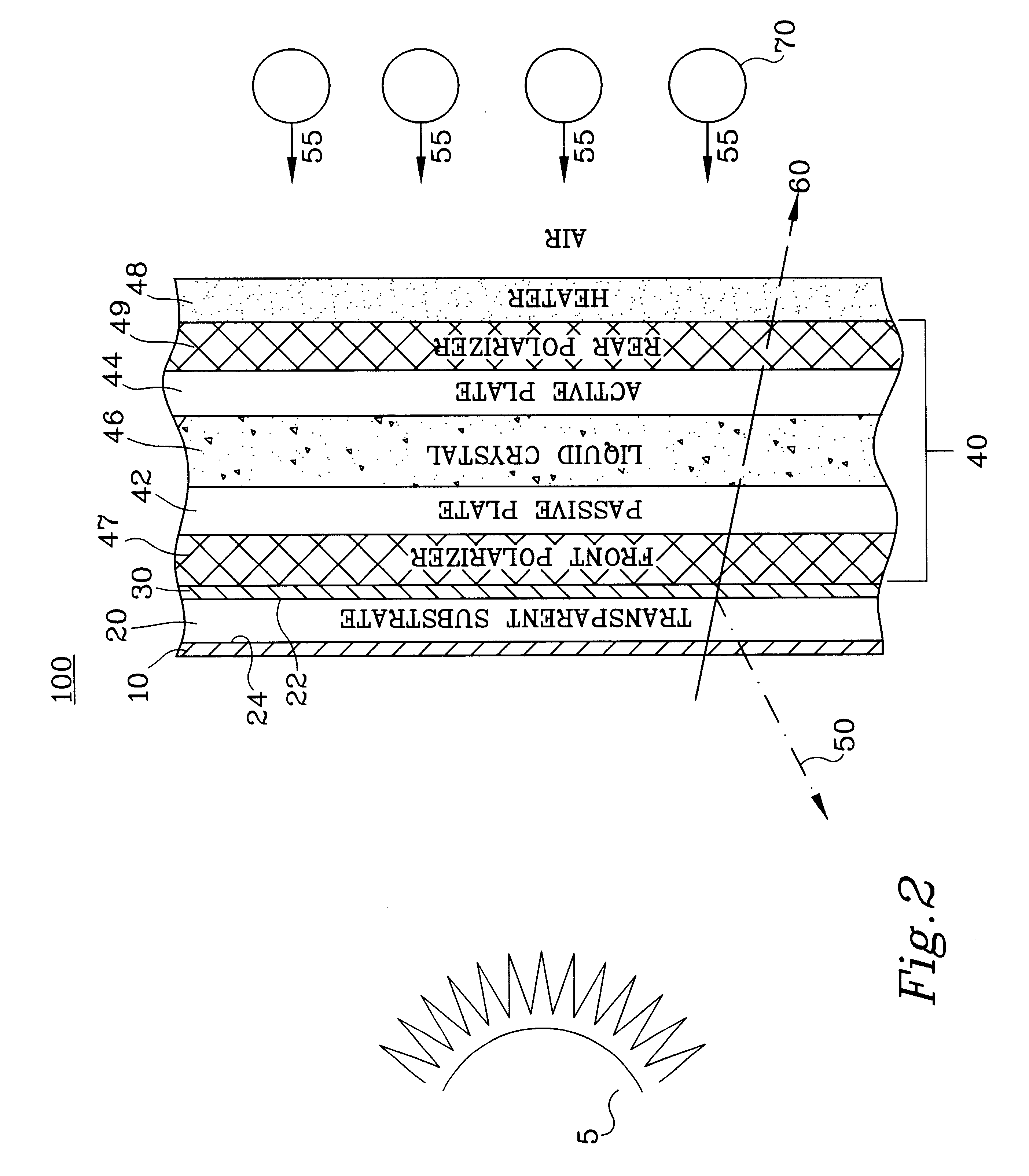
Also, the present invention comprises a method for reducing solar loading on display devices. The method comprises the steps of selecting a suitable reflective material to reflect a predetermined wavelength range of the radiant energy; and providing the reflective material between the absorptive material of the display device and the external radiant energy source.
The reflecti

Problems solved by technology

All of these types of display devices and many others are likely to be exposed to the sun or radiant energy thus creating a thermal rise due to solar exposure thereon (solar loading).
In most display devices that are subject to receiving radiant energy, the following problems are posed.
The display device often experiences a temperature rise of the display device due to solar loading or other radiant energy sources.
This solar loading problem is intensified when cooling methods, such as forced cooling air, are unavailable.
As a result, the display device can be permanently damaged, such as is the case with polarizers and adhesives associated with LCDs when exposed to temperatures in excess of 100.degree. C.
Also, sometimes the liquid crystal material of an LCD device "clears" (exceeds its operating capability due to the temperature of the liquid crystal).
This approach alleviates the problem, but the availability of these materials is limited.
Also, this approach is not practical for commercially-available liquid crystal materials due to a significant cost factor.
This approach is practical only when cooling air is available, which is not always the case.
Thus, a need exists to reduce the solar loading on display devices that are subjected to a thermally-challenging environment.

Method used


Image

  • Method of and apparatuses for reducing infrared loading on display devices
  • Method of and apparatuses for reducing infrared loading on display devices
  • Method of and apparatuses for reducing infrared loading on display devices

Examples


Embodiment Construction

Although the following description of the present invention is provided with reference to a light-transmitting type active-matrix LCD device, the present invention is not restricted to this particular type of display. The present invention is directed toward any display that is used in an environment where solar loading on the display device is of concern, such as active-matrix LCDs, passive-matrix LCDs, reflective LCDs, transreflective LCDs, segmented LCDs, cholesteric LCDs, non-matrix LCDs, CRTs, etc. The following description is provided with respect to an LCD for convenience in introducing the present invention, but the present invention applies to any display device experiencing solar loading. Additionally, those skilled in the art will recognize that the present invention is limited neither to active-matrix LCD devices in general nor to LCD devices of any certain addressability (e.g., 640 by 480). In this regard, the present invention can also be used with any form of passive-...


PUM


Abstract

Methods of and apparatuses for reducing the solar or infrared loading on display devices. A reflective material is positioned between a radiant energy source and the absorptive material of a display device to reflect wavelengths of radiant energy in the infrared or near-infrared range. The reflective material allows visible radiant energy to be transmitted, while reflecting the infrared radiant energy to reduce the infrared loading on the display device. The present invention reduces the temperature rise of the display device due to infrared loading by reflection rather than absorption of the radiant energy, while preserving the integrity of the visible wavelength range. The reflective material reduces the infrared loading on the display device by up to 50%.

Description

I. CROSS-REFERENCE TO RELATED APPLICATIONSNot applicable.II. BACKGROUND OF THE INVENTIONThe present invention relates generally to the field of display devices, such as liquid crystal displays ("LCDs"), cathode ray tubes ("CRTs"), and similar display devices. More specifically, the present invention relates to methods of and apparatuses for reducing the infrared loading (e.g., solar loading from the sun) on such display devices by using a reflective material to reflect infrared energy.A "display" is an image output device that provides information to an observer in a visible form. A "liquid crystal display" ("LCD") is a display device that includes a liquid crystal cell with a light transmission characteristic that can be controlled in parts of the cell by an array of light control units to cause presentation of an image. A "liquid crystal cell" is an enclosure containing a liquid crystal material. An "active-matrix liquid-crystal display" ("AMLCD") is an LCD in which each light con...

Claims


Application Information

Patent Timeline
IPC IPC(8): G02F1/13G02F1/1335G02B5/28G02B5/26G02B5/30G09F9/00
CPCG02F1/133509G02F2201/083
Inventor HABING, ROBERT D.HENZ, JAMES M.MANER, RANDY M.WOOD, TEDDY J.
Owner HONEYWELL INC
Learn More