Tiltable infeed and outfeed saw table

a saw table and infeed technology, applied in the direction of metal sawing devices, metal-working machine components, manufacturing tools, etc., can solve the problems of affecting the inability to meet the requirements of the cutting machine, etc., to achieve the effect of reducing the number of sawings, and improving the quality of the produ

Inactive Publication Date: 2001-04-10
STODDARD H PYLE REVOCABLE LIVING TRUST DATED JULY 17 1991
View PDF14 Cites 46 Cited by
  • Summary
  • Abstract
  • Description
  • Claims
  • Application Information

AI Technical Summary

Benefits of technology

Workpiece 40 is placed on the horizontal plane surface of first tiltable table 44a, where it comes under control of computer 38. Workpiece 40 is tipped about the longitudinal or first axis 66 of table 44a from its face to edge, or vice versa, to achieve optimum orientation for minimum elapsed time for the subsequent operations. Workpiece 40 is then tilted to first predetermined angle .alpha. to the horizontal, by tilting of first tiltable table 44a about th...

Problems solved by technology

Otherwise, it became very expensive to produce them for a single truss, since adjustments had to be made between the cutting of each different component.
1. since jack rafters have at least one end thereof cut at a composite angle, i.e., an angle both to the edges and to the faces, the lengths of opposite faces (and/or edges) thereof are unequal; and
2. hip and valley rafters have at least one end which requires two cuts, both of which are at composite angles (making a compound angle) to the faces and edges, but which are usually at right angles to each other (although not necessarily). Although the lengths on the faces (or edges) may be equal, the length on the measuring line will be different (greater) than both.
Present machinery for making cuts to produce composite or compound angles on roof structure components still requires substantial hand labor in the set-up and/or operation of cutting equipment.
A disadvantage of this method is that the measuring line of the lumber shifts laterally across the table top and shifts vertically as the gauge length is changed for different roof slopes, causing the reference point for length measurement to change.
This shifting makes the gauge method inaccurate for making precision compound or composite angle cuts using a push-feed...

Method used


Image

  • Tiltable infeed and outfeed saw table
  • Tiltable infeed and outfeed saw table
  • Tiltable infeed and outfeed saw table

Examples


Embodiment Construction

Certain dimensions, and the way they are determined, are critical to understanding the novel functions and operations of the present invention.

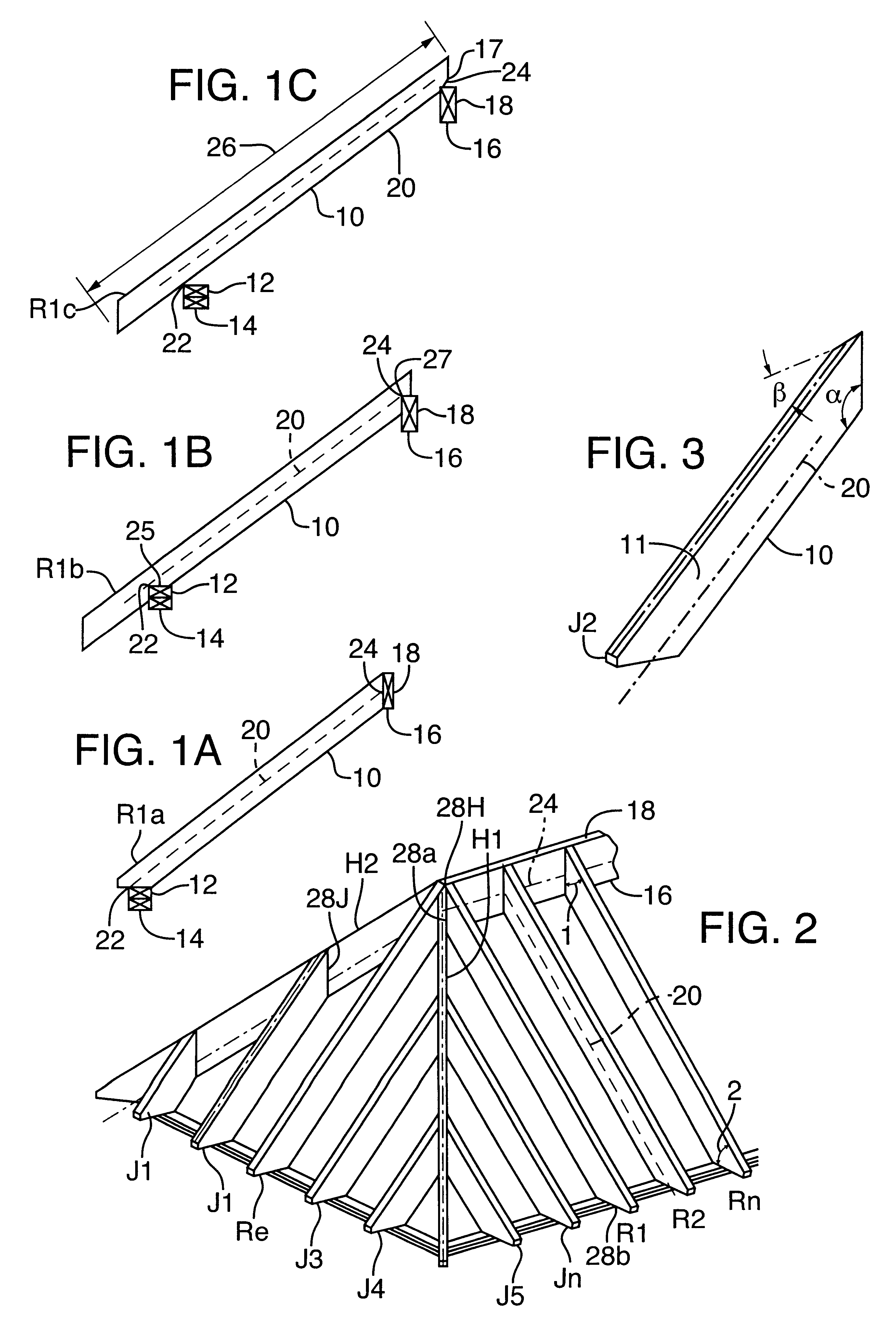
FIGS. 1A-C show typical regular rafters R1a, R1b, and R1c for convenience, spanning from double top plates 14 to ridge beam 18. Each of these arrangements is used in construction, although 1A and 1B are used more often at the present time than 1C, which is an older method of construction. A detailed examination of each will help in understanding the concepts involved in determining rafter length.

In FIG. 1A, rafter R1a rests on double top plates 14 on the outer end, and on ridge beam 18 on the inner end. Lower edge 10 intersects inner edge 12 of double top plate 14 and lower edge 16 of ridge beam 18. "Measuring line" 20 is defined as a line, parallel to lower edge 10, extending across outer edge 22 of plate 14 to its intersection with the face of ridge beam 18. Line 24 on beam 18, which is parallel to lower edge 16 thereof, and passes through ...


PUM

PropertyMeasurementUnit
Angleaaaaaaaaaa
Dimensionaaaaaaaaaa

Abstract

An apparatus for sequentially and automatically cutting a piece of dimension lumber at a number of predetermined angles to produce a building component, such as a rafter or truss web or chord, with composite or compound angles, is disclosed. The apparatus includes infeed and outfeed tables tiltable about a longitudinal axis and equipped with fences along which a workpiece moves longitudinally via moving devices. Clamps hold the workpiece at different positions relative to a cutting station during a cutting operation. A cutter, which for example includes a circular saw blade, is mounted for a positioning movement about a vertical axis at the cutting station, as well as for vertical movement to cut a workpiece at a predetermined composite or compound angle. The entire lumber cutting process at both ends of the workpiece, including lumber movement on the table past the cutting station, angular cutter and table adjustment, cutter movement, and clamping and unclamping, is under the control of a programmable computer operating in conjunction with appropriate sensors and pulse counters on the equipment.

Description

This invention relates, in general, to an apparatus for the physical preparation of semi-finished material into finished components; e.g., dimension lumber into finished rafters having predetermined lengths and angles at the ends thereof, for use in building construction.In particular, this invention relates to an apparatus, including a novel tiltable table and adjustable cutting device, for processing workpieces of semi-finished material into finished components for assembly, and to a computer control and program for controlling same.DOCUMENT DISCLOSURE DEPOSITThis invention is described and disclosed in a document and drawings prepared and filed by Applicant herein, in the Document Disclosure Program of the U.S. Patent and Trademark Office, Ser. No. 284,271, filed Jun. 14, 1991.Most lumber used in the construction industry is known as dimension lumber, which the present invention is intended to use. Dimension lumber has opposite sides parallel, with adjacent sides forming a right ...

Claims


Application Information

Patent Timeline
IPC IPC(8): B23D45/02B23D47/04B23D45/14B23D47/00B23D45/00
CPCB23D45/024B23D45/14B23D47/04Y10T83/05Y10T83/051Y10T83/141Y10T83/2198Y10T83/463Y10T83/727Y10T83/7493Y10T83/7697Y10T83/7705Y10T83/7722Y10T83/7726Y10T83/7772Y10T83/8773
Inventor PYLE, STODDARD H.
Owner STODDARD H PYLE REVOCABLE LIVING TRUST DATED JULY 17 1991
Why Eureka
Try Eureka