System of trajectory planning for robotic manipulators based on pre-defined time-optimum trajectory shapes

a robotic manipulator and trajectory planning technology, applied in the field of robotic manipulators, can solve the problems of limited transfer time, fraught problems, and additional constraints, such as limited velocity and jerk, to achieve the effect of generating the known multi-arm robotic manipulator, and avoiding the effect of jerking

Inactive Publication Date: 2001-04-10
BOOKS AUTOMATION US LLC
View PDF3 Cites 114 Cited by
  • Summary
  • Abstract
  • Description
  • Claims
  • Application Information

AI Technical Summary

Benefits of technology

It will therefore be appreciated from the foregoing description that the present invention offers many advantages over the systems of the prior art, such as, its reliability for any combination of arm dimensions, speed, and departure / destination positions, and the elimination of all types of defects since it results in ideal acceleration profiles. Further, the resulting trajectories are time-optimal, or suboptimal for certain radial moves of dual-arm frog-leg robots, and achieves shorter travel times due to the constant jerk limit imposed on the center of the end effector for straight-line moves. It offers easy-to-track trajectories for straight-line moves with smooth acceleration profiles, and is computationally efficient, typically being more than 100.times. faster than the existing iterative approach. Due to the faster computation capability, shorter abort times and abort travel distances are guaranteed. The invention is less memory demanding with a maximum of 12 trajectory nodes stored (for the categories of moves considered ), and it eliminates different settings of the trajectory generator for different arms and speeds. It is applicable to all of the arms of the transfer apparatus, including two-link and frog-leg designs and particularly "BiSymmetric" and "Leapfrog" arm designs, and supports compound moves with a blended transfer path.

Problems solved by technology

Therefore, the substrate will slide if the inertial force at the substrate exceeds the holding force securing it to the end effector, so that the transfer time is limited by the magnitude of this holding force.
Furthermore, additional constraints, such as limited velocity and jerk, are typically required for safe operation and trajectory tracking reasons.
However, the present state of the available methods, in this exemplary approach and other embodiments, for achieving iterative trajectory generation with the known multi-arm robotic manipulators is fraught with problems.
For example, generally among these methods the existence of a reliable solution to the iterative computation is not guaranteed and the calculations are computationally demanding and time consuming, leading to delays, especially in the abort function.
Suboptimal acceleration profiles and defective trajectory profiles cause acceleration tracking difficulties and throughput loss.
Another drawback of the existing approach, typified by that in U.S. Pat. No. 5,655,060, is that individual moves must be executed sequentially with no provision for blending simple moves into a single trajectory to create a single smooth transfer path.
The sequential execution requires stops between the individual moves and increases the overall travel time.

Method used


Image

  • System of trajectory planning for robotic manipulators based on pre-defined time-optimum trajectory shapes
  • System of trajectory planning for robotic manipulators based on pre-defined time-optimum trajectory shapes
  • System of trajectory planning for robotic manipulators based on pre-defined time-optimum trajectory shapes

Examples


example 2

tions that must be satisfied for the shape in FIG. 19, i.e., the simplest shape for a straight-line move, are:

max .vertline.j.vertline..ltoreq.j.sub.max and max .vertline.a.vertline..ltoreq.a.sub.max and t.epsilon.(t.sub.0, t.sub.2) t.epsilon.(t.sub.0, t.sub.2) max .vertline.v.vertline..ltoreq.v.sub.max t.epsilon.(t.sub.0, t.sub.2).

Trajectories generated by the method of the invention are completely defined by a set of nodal points which typically may include time, position, velocity, acceleration, jerk, and jerk rate. The corresponding position, velocity, and acceleration profiles are constructed from the nodal points using the set of equations associated with the selected trajectory shape.

The generic trajectory shapes for the basic categories of moves, their mathematical description, and the depiction of the associated fundamental shapes will now be described.

Single-arm Robot Move Along a Stright Line

To begin with, a move of a single-arm robot along a straight line in accordance w...

case 1

Amax.ltoreq.a.sub.Bmax ; and

Case 2: a.sub.Amax >a.sub.Bmax.

Since acceleration of end effector B never violates a.sub.Amax during radial moves for the known designs of dual-arm frog-leg robots, the acceleration limit a.sub.Bmax never becomes active when a.sub.Amax.ltoreq.a.sub.Bmax. Consequently, the same trajectory shapes can be used in Case 1 as for a straight-line move of a single-arm robot as described above.

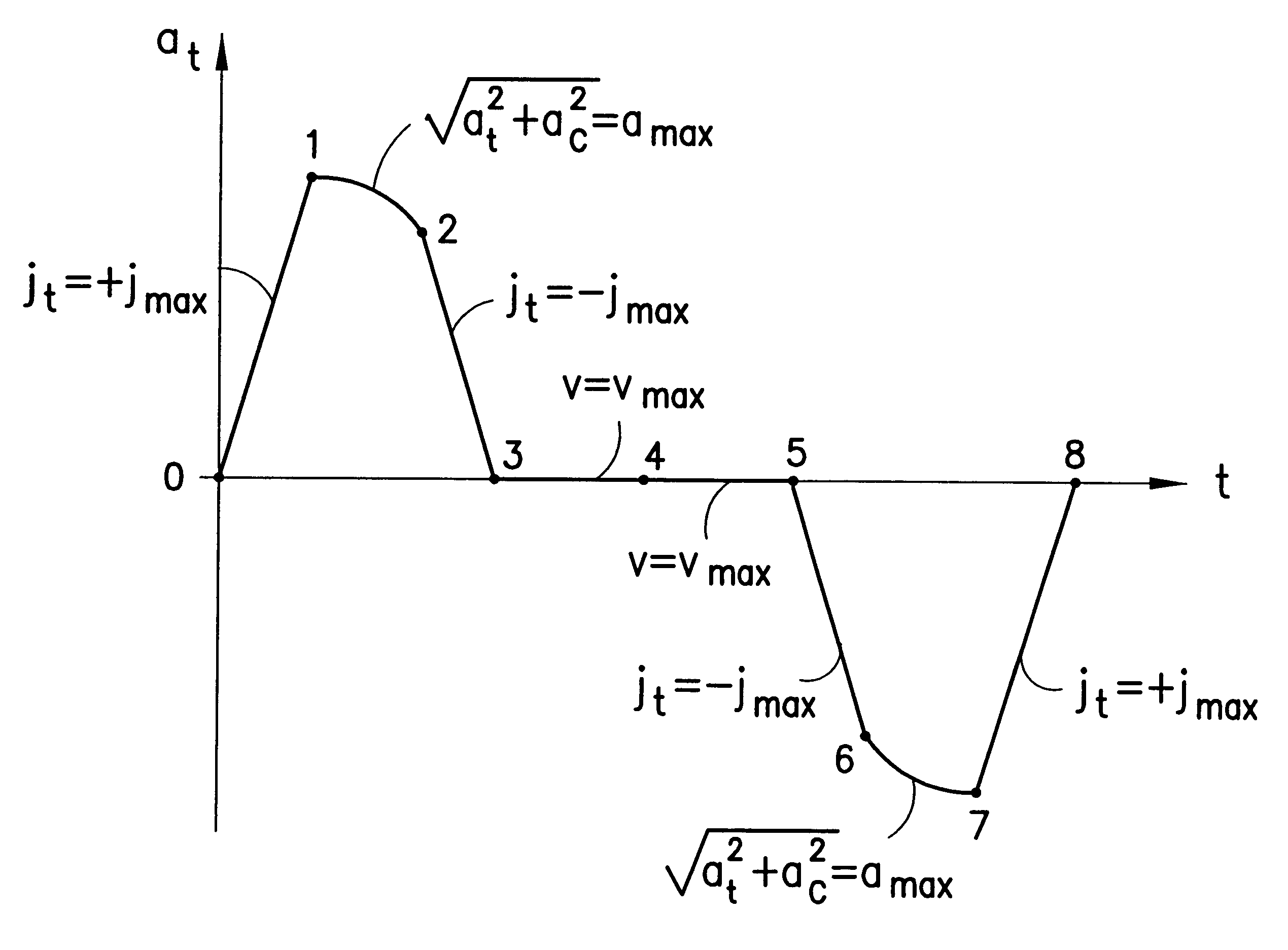
The generic trajectory shape for Case 2 is depicted in FIG. 35. It is composed of 7 segments:

Segment 0-1: j.sub.A =+j.sub.Amax

Segment 1-2: a.sub.B =-a.sub.Bmax

Segment 2-3: j.sub.A =+j.sub.Amax

Segment 3-4: a.sub.A =a.sub.Alim

Segment 4-5: j.sub.A =-j.sub.Amax

Segment 5-6: a.sub.A =-a.sub.Amax

Segment 6-7: j.sub.A =+j.sub.Amax

At the cost of a slight deviation from the optimum solution, the value of a.sub.Alim is selected so that max(a.sub.B)=+a.sub.Bmax. Due to this simplification the number of necessary fundamental trajectory shapes is reduced substantially. The position, velocit...


PUM


Abstract

A system for providing the reliable and numerically efficient generation of time-optimum trajectories with easy-to-track or continuous acceleration profiles for simple and blended moves of single- and multi-arm robotic manipulators, such as an extension and retraction move along a straight line or a rotary move following a circular arc, with velocity, acceleration, jerk, and jerk rate constraints. A time-optimum trajectory is the set of the position, velocity, and acceleration profiles which describe the move of a selected end effector along a given path in the shortest time possible without violating given constraints, with a special case being an optimum abort trajectory, which brings the moving arm into complete rest in the shortest time. The invention involves firstly identifying the set of fundamental trajectory shapes which cover all possible combinations of constraints for a given category of moves, e.g., a move along a straight line or along a circular arc; next, decomposing the fundamental shapes into segments where a single constraint is active; and, then, determining the time optimum paths in the segments. As a result, a unique design of time-optimum trajectories is produced based on a set of pre-defined trajectory shapes. The invention also involves the blending of simple moves into a single trajectory by decomposing trajectories of the individual moves into their orthogonal components and overlapping them for a given time interval, which results in a non-stop move along a smooth transfer path.

Description

1. Field of the InventionThe present invention relates to robotic manipulators and, more particularly, to a method and means for the reliable and numerically efficient generation of constrained time-optimum trajectories for the simple and compound or blended moves of single-arm, dual-arm, and multi-arm robotic manipulators.2. Prior ArtSingle-arm, dual-arm, and multi-arm, i.e., single end effector, dual end effector, and multi end effector, robotic manipulators are used in various types of transport apparatus in embodiments well known in the prior art. Examples of typical transport apparatus including such embodiments are described in U.S. Pat. Nos. 4,730,976, 5,180,276, 5,404,894, 5,431,529, 5,647,724, 5,655,060, 5,765,983, and in pending U.S. application Ser. No. 09 / 163,844, the latter having an assignee in common with this application, and the disclosures of all of which are incorporated herein by reference. In an embodiment such as used with a substrate transport apparatus, the t...

Claims


Application Information

Patent Timeline
Patent Type & Authority Patents(United States)
IPC IPC(8): B25J9/16G06Q50/04B25J9/10B25J9/18G06F17/13G06F19/00G06Q10/06
CPCB25J9/1664G05B2219/40395G05B2219/40454G05B2219/40519Y10S414/137Y10S414/136Y10S414/135G06Q10/06G06Q50/04
Inventor HOSEK, MARTINELMALI, HAKAN
Owner BOOKS AUTOMATION US LLC
Why Eureka
Try Eureka