Machine tool

a technology of machine tools and tools, applied in the field of machine tools, can solve the problems of adversely affecting the precision of machining, deformation structure and large scale of the entire machine, etc., and achieve the effect of increasing productivity, ensuring precision, and increasing precision

Inactive Publication Date: 2001-04-24
PANASONIC CORP
View PDF15 Cites 33 Cited by
  • Summary
  • Abstract
  • Description
  • Claims
  • Application Information

AI Technical Summary

Benefits of technology

Relative positions between the chuck means and the spindle is variably determined by moving the table disposed on one side of the body frame with respect to the axial center of the spindle disposed within the body frame. The mechanism for variably determining the positional relationship between the spindle and a workpiece held by the chuck means is comprised of the body frame and the table on one side thereof in abutment with each other, and includes no roundabout members such as a cantilevered column, providing no spaces between each member. The entire design of the machine tool can be thus compactly constructed with small and light parts yet keeping high rigidity. High-speed and highly accurate machining is thereby accomplished while minimizing the structure in size, weight, and cost. Further, the entire structure of the machine tool can be made approximately symmetrical around the spindle as the axis of symmetry, which restrains adverse effects of thermal deflection caused by changes in temperature which leads to errors in machining. It is to be understood that the axial center of the spindle may be arranged parallel as well as vertical to a horizontal plane.
Further, a pair of chuck means may be disposed in the X-axis table in parallel with each other along the Y-axis direction, and the Y-axis table may be arranged to be movable between farthest ends where one chuck means positions just above the opening in the base plate, the base plate having a pair of another openings through which a workpiece if removed from and fed to the other chuck means when the Y-axis table is located at a given farthest end. While a workpiece held by one chuck means is being machined, another workpiece can be removed from and fed to the other chuck means, which reduces the time for exchanging workpieces, thereby increasing productivity.

Problems solved by technology

To meet these requirements, relatively larger members precisely constructed are necessary, causing the entire machine to be larger, heavier, more expensive, and to occupy a larger space in a factory line for installation.
Another problem is attributable to the detoured structure and the large scale of the entire machine.
Thermal deflection caused by changes in temperature has greater influence on the mechanisms, adversely affecting the precision of machining.

Method used


Image

  • Machine tool
  • Machine tool
  • Machine tool

Examples


Embodiment Construction

Preferred embodiments of the invention will be hereinafter described with reference to the accompanying drawings.

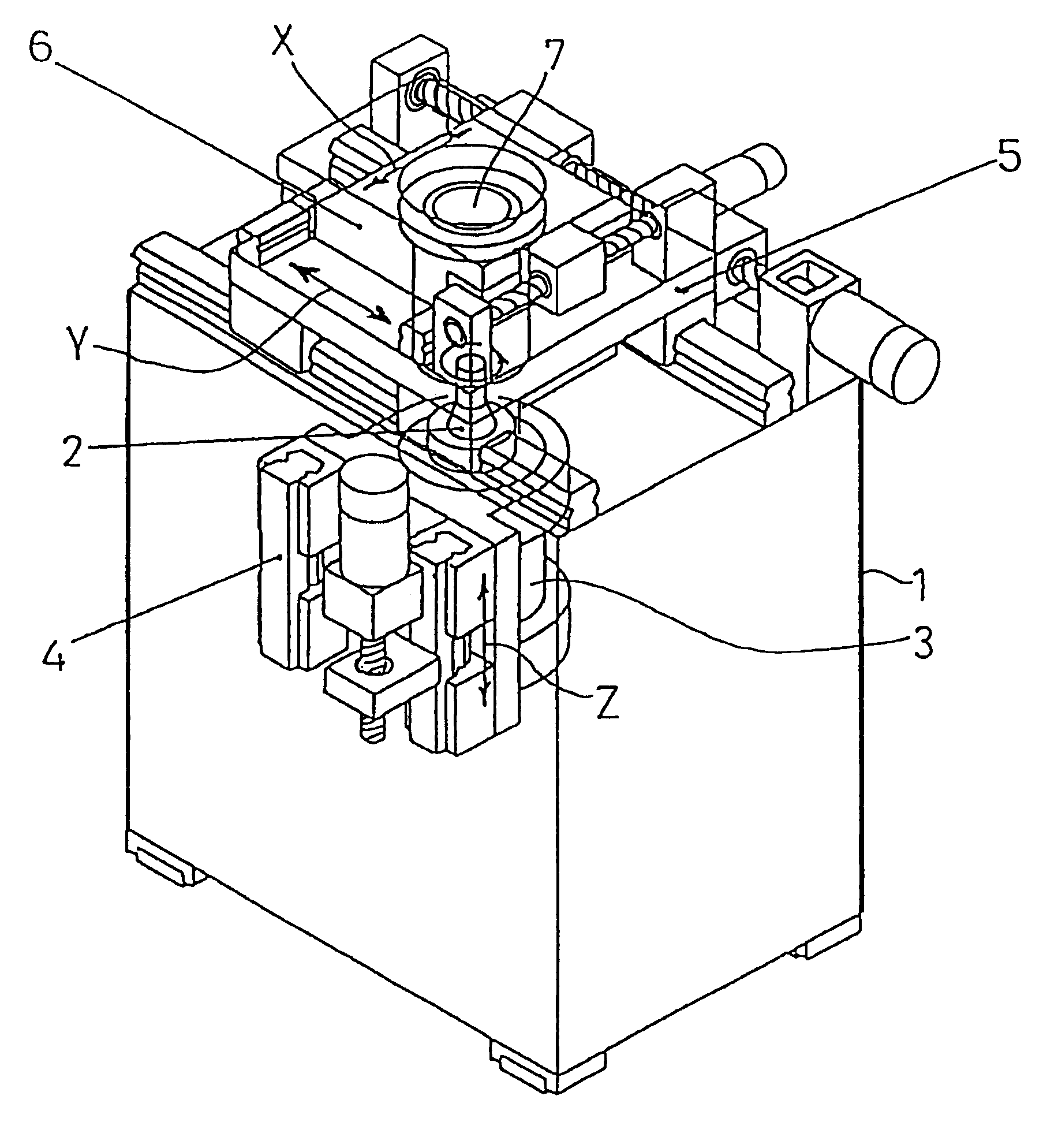
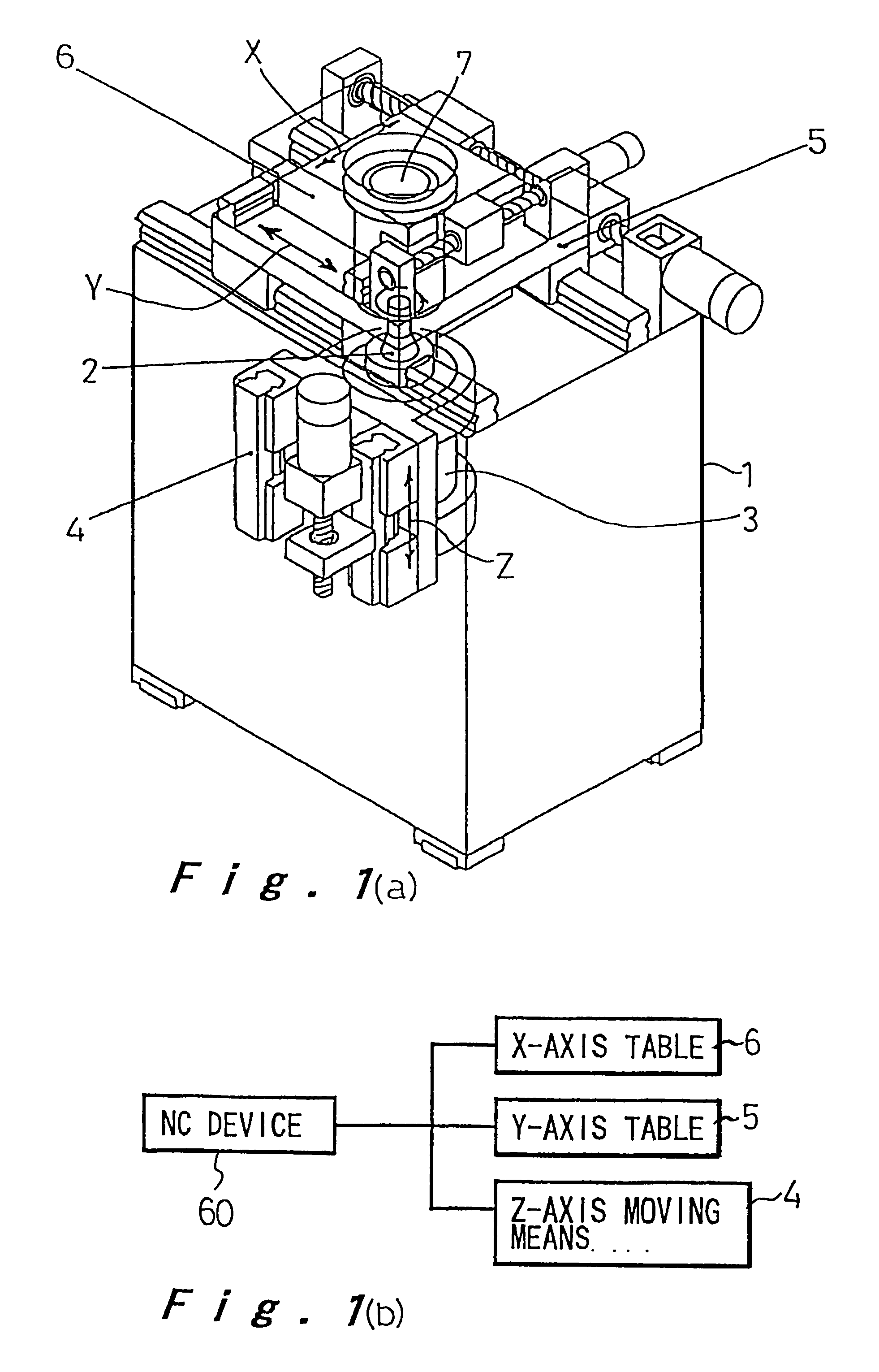
FIG. 1(a) is a perspective view which schematically shows the entire configuration of the present invention. In FIG. 1(a), a box-like body frame 1 of approximately a rectangular parallelepiped encases a spindle 2 standing upright along a Z-axis perpendicular to a horizontal direction, a rotary driver 3 for driving the spindle 2, and a Z-axis moving means 4 for moving the spindle 2 and its rotary driver 3 along the Z-axis direction. On the top surface of the body frame 1 is a Y-axis table 5 being movable along the Y-axis, on which an X-axis table 6 is mounted for movement along the X-axis. A chuck means 7 for holding a workpiece is disposed on the X-axis table 6. The Z-axis moving means 4, the Y-axis table 5, and the X-axis table 6 are operated through a numerical control device 60 as shown in FIG. 1(b).

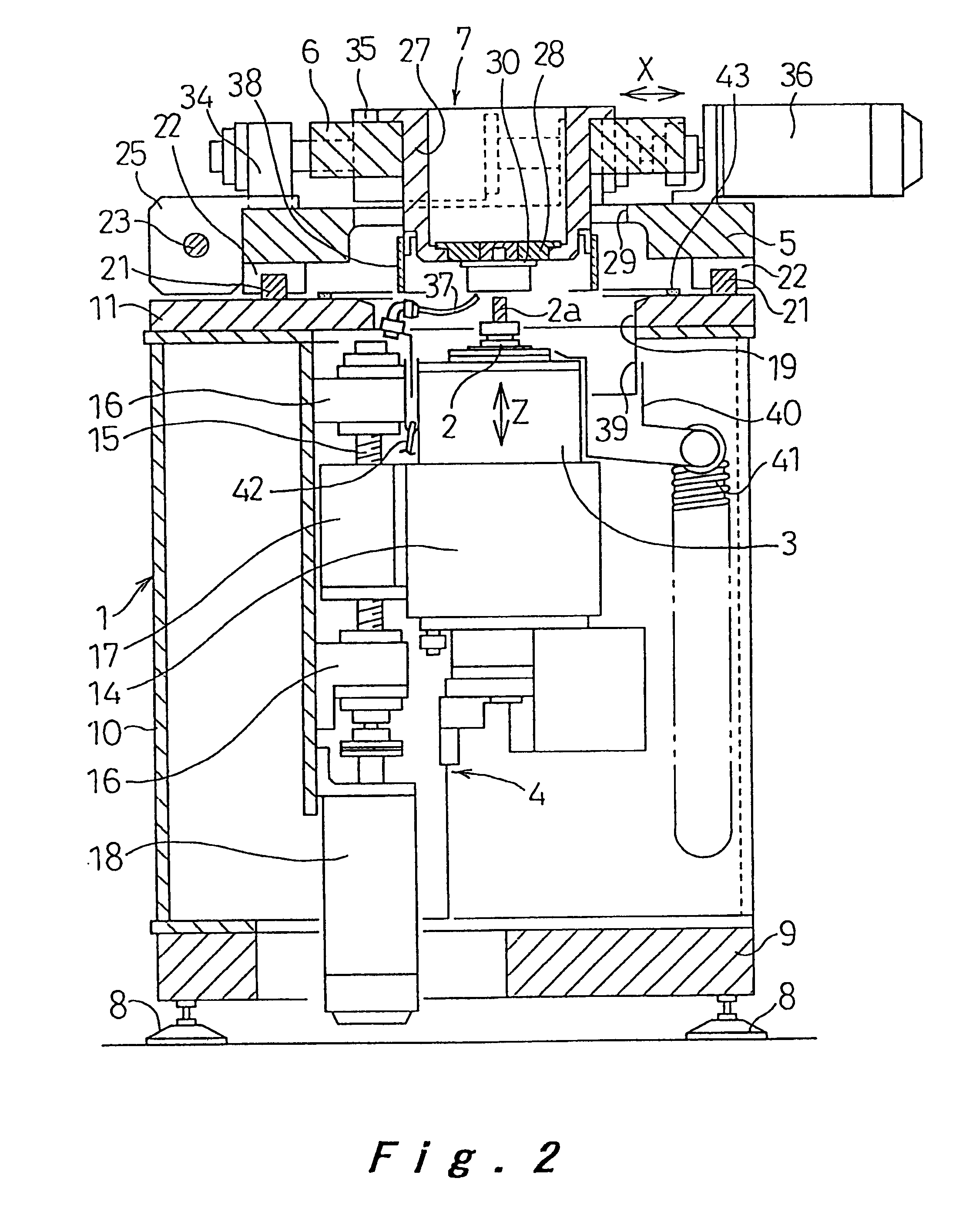
Referring now to FIGS. 2 to 6 showing more detailed configurations of ...


PUM

PropertyMeasurementUnit
symmetryaaaaaaaaaa
distanceaaaaaaaaaa
speedaaaaaaaaaa

Abstract

A machine tool of small scale, light weight, and low cost, yet accomplishing a high degree of precision in machining. A spindle (2) is encased in a body frame (1) and disposed preferably in such a manner that the spindle (2) is movable along an axial center thereof or Z-axis direction by means of a Z-axis moving means (4). Either Y-axis table (5) or an X-axis table (6), at least being capable of moving along X-axis or Y-axis direction, or both is provided at one end of the spindle (2) on one side of the body frame (1) and arranged to be vertical with respect to the axial center of the spindle (2).

Description

The present invention relates to a machine tool.In a conventional machine tool with a vertical spindle, the spindle is supported by a column in such a way that the spindle is movable along its axial direction or the Z-axis, and the column is either directly or indirectly supported on a base. In an exemplary arrangement shown in FIG. 21(a), an X-axis table 72 being movable in the X-axis direction is mounted on a base 71, and a column 73 serving as a Y-axis table being movable in the Y-axis direction is mounted on the X-axis table 72. A spindle head 74 is supported by the column 73 movably along the Z-axis, and a work bed 75 is connected to the base 71. In another arrangement shown in FIG. 21(b), an X-axis table 76 serving as a work bed and the column 73 serving as a Y-axis table for movement in the Y-axis direction are mounted on the base 71. The spindle head 74 is supported by the column 73 movably along the Z-axis direction. U.S. Pat. No. 5,439,431 typically discloses such type of ...

Claims


Application Information

Patent Timeline
Patent Type & Authority Patents(United States)
IPC IPC(8): B23Q11/00B23Q1/62B23Q11/08B23Q11/10B23Q1/00B23Q1/01B23Q1/25G05B19/4062G05B19/406
CPCB23Q1/012B23Q1/621B23Q1/625B23Q1/626B23Q11/0046B23Q11/0053B23Q11/08B23Q11/10G05B19/4062B23Q1/015Y10T409/309072Y10T29/5107Y10T409/3056Y10T483/115Y10T409/30392Y10T408/47Y10T409/30924B23Q39/024B23Q2039/002
Inventor OKUTANI, NORIOOKADA, TOSHIYUKIISHII, YOSHIMICHI
Owner PANASONIC CORP
Why Eureka
Try Eureka