Constant flow fluid pump

a fluid pump and constant flow technology, applied in the direction of positive displacement liquid engine, separation process, instruments, etc., can solve the problems of constant flow, high cost and complexity of double-aggressive pumps, and constant pressure source that doesn't provide constant flow

Inactive Publication Date: 2001-05-08
BECTON DICKINSON & CO
View PDF12 Cites 64 Cited by
  • Summary
  • Abstract
  • Description
  • Claims
  • Application Information

AI Technical Summary

Problems solved by technology

However the application of a constant pressure to a fluid may not result in a constant flow if the resistance to flow changes.
A problem with positive displacement pumps is that the rotary displacement of the electric motor must be converted to a linear displacement in order to activate the pump and thereby pump the fluid, i.e., both the diaphragm and the reciprocating piston are driven by a powered rod of some type that receives its linear motion by means of a reciprocating crankshaft.
However these types of double acting pumps are expensive and complex.
The problems with these two compensation methods is that the tank must have a very small height to preve

Method used


Image

  • Constant flow fluid pump
  • Constant flow fluid pump
  • Constant flow fluid pump

Examples


Embodiment Construction

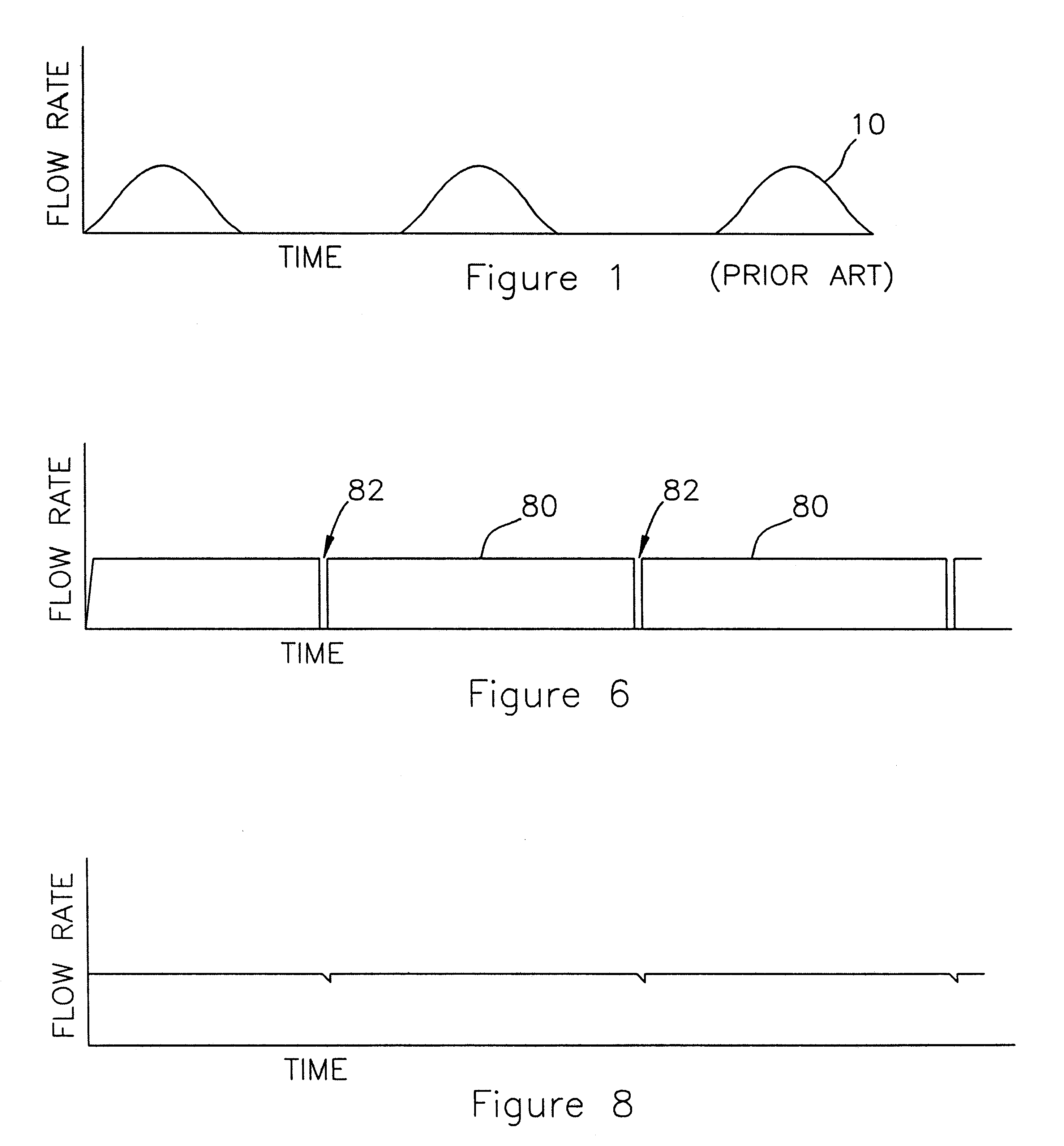
Referring now to the drawings and to FIG. 1 in particular there is shown a graph 10 of the prior art sinusoidal output of a rotary positive displacement pump driven by an electric motor. Both the pressure and volume output of the pump are shown as a half rectified sine wave, which graph replicates the actual output experienced by displacement pumps of the prior art.

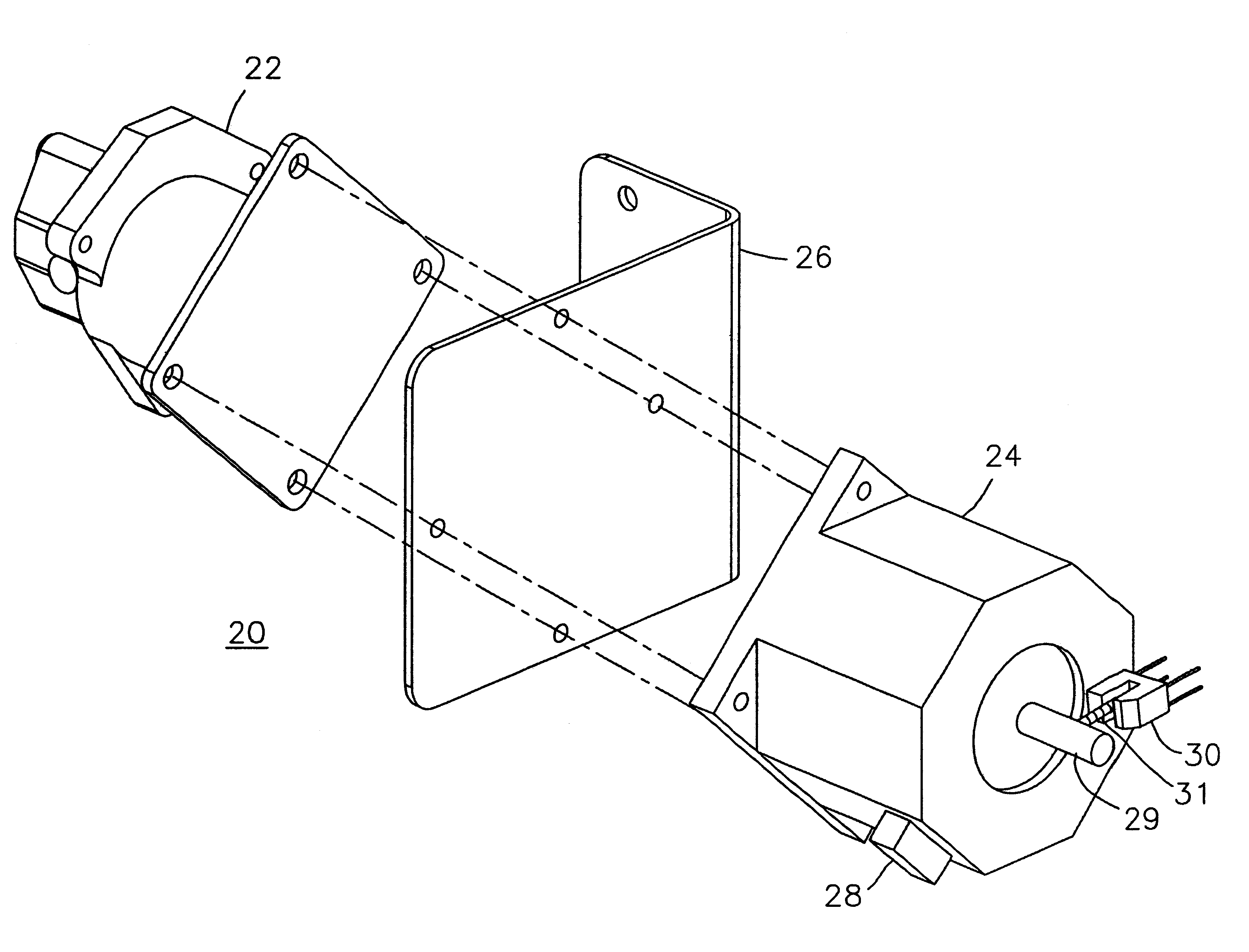
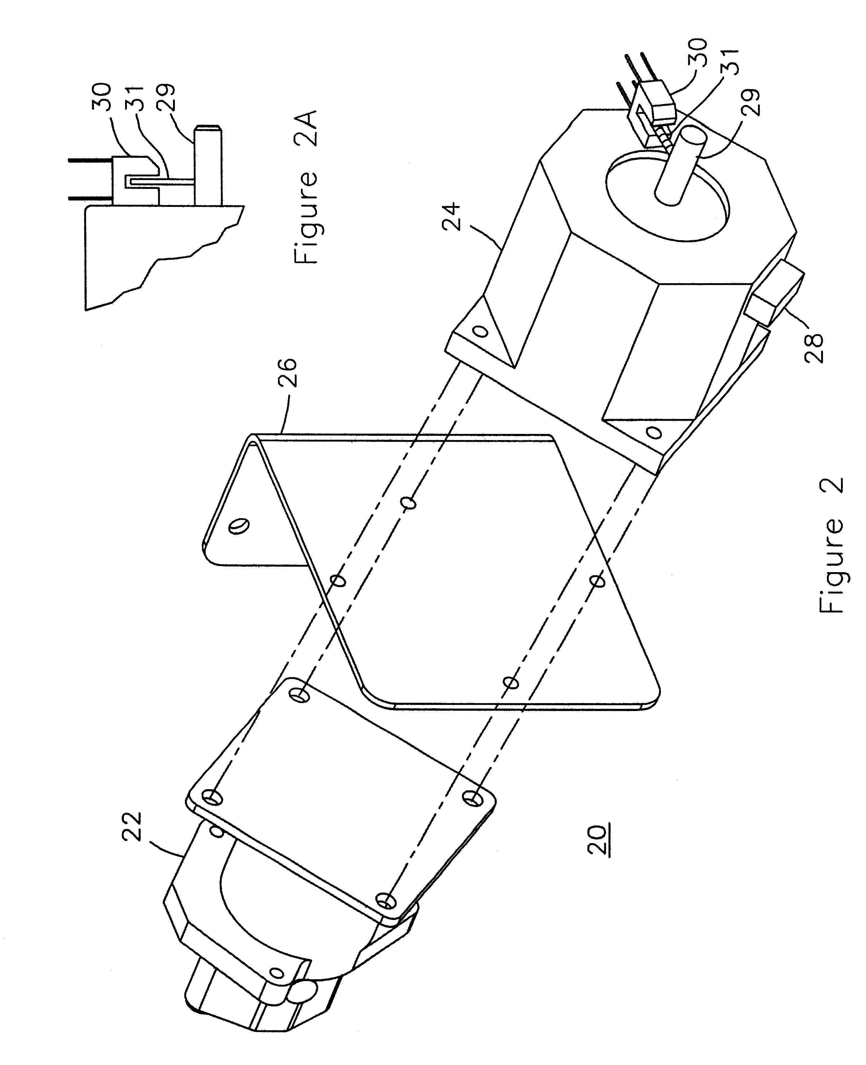
Referring now to FIGS. 2 and 2A there are shown pictorial views of a rotary positive displacement pump unit 20 constructed according to the teachings of the invention. Pump unit 20 includes positive displacement pump 22, mechanically coupled with and driven by stepper motor 24, having mounting bracket 26 disposed there between. Stepper motor 24 is adapted for connection to outside electrical power by means of electrical connector 28. Electrical power supplied to stepper motor 24 is conditioned by a control means of the invention so as to control the output of pump 22 to replicate as closely as possible a constant step fun...


PUM


Abstract

The present invention is a means and method for providing constant output flow from a fluid pump. The invention does this by controlling the radial speed of the pump motor during discreet segments of the motor's 360° angular/radial path through a revolution of the pump. The electric pump motor is controlled throughout the 360° radial path by employing a control means for controlling the speed of actuation of the radial steps of a stepper motor throughout the 360° path of rotation of the stepper motor. Control means for controlling the speed of the discreet steps of the stepper motor comprises at least a memory means, a counting means and an amplification means.

Description

1. Field of the InventionThe invention relates in general to a constant flow fluid pump and in particular to means and method for reduction of pressure and flow pulsations in a fluid pump by selectively controlling the rotational speed of the pump driving motor at any one of a predetermined number of discrete rotational steps around the 360.degree. periphery of the driving motor rotation.2. Description of the Related ArtThere are many applications for analyzing blood and other fluids for which it is important to move the fluid to be examined at a uniform rate through testing / analyzing equipment, such as a flow cytometer. These fluids are usually driven by a constant pressure source. However the application of a constant pressure to a fluid may not result in a constant flow if the resistance to flow changes. For constant flow, the force pumps for driving these fluids are either of the diaphragm or reciprocating piston type of positive displacement pump that is actuated by an electric...

Claims


Application Information

Patent Timeline
IPC IPC(8): F04B49/06F04B11/00
CPCF04B11/0041F04B49/065G01N15/1404
Inventor CHASE, ERIC
Owner BECTON DICKINSON & CO
Why Eureka
Try Eureka