
Electromagnetic forming apparatus

a technology of forming apparatus and electromagnetic field, which is applied in the direction of welding apparatus, non-electric welding apparatus, manufacturing tools, etc., can solve the problems of pulsating force, technical difficulties, and practicability

Inactive Publication Date: 2001-05-08
INFINITY IP COMMERCIALIZATION ISRAEL LTD
View PDF13 Cites 47 Cited by
  • Summary
  • Abstract
  • Description
  • Claims
  • Application Information

AI Technical Summary

Benefits of technology

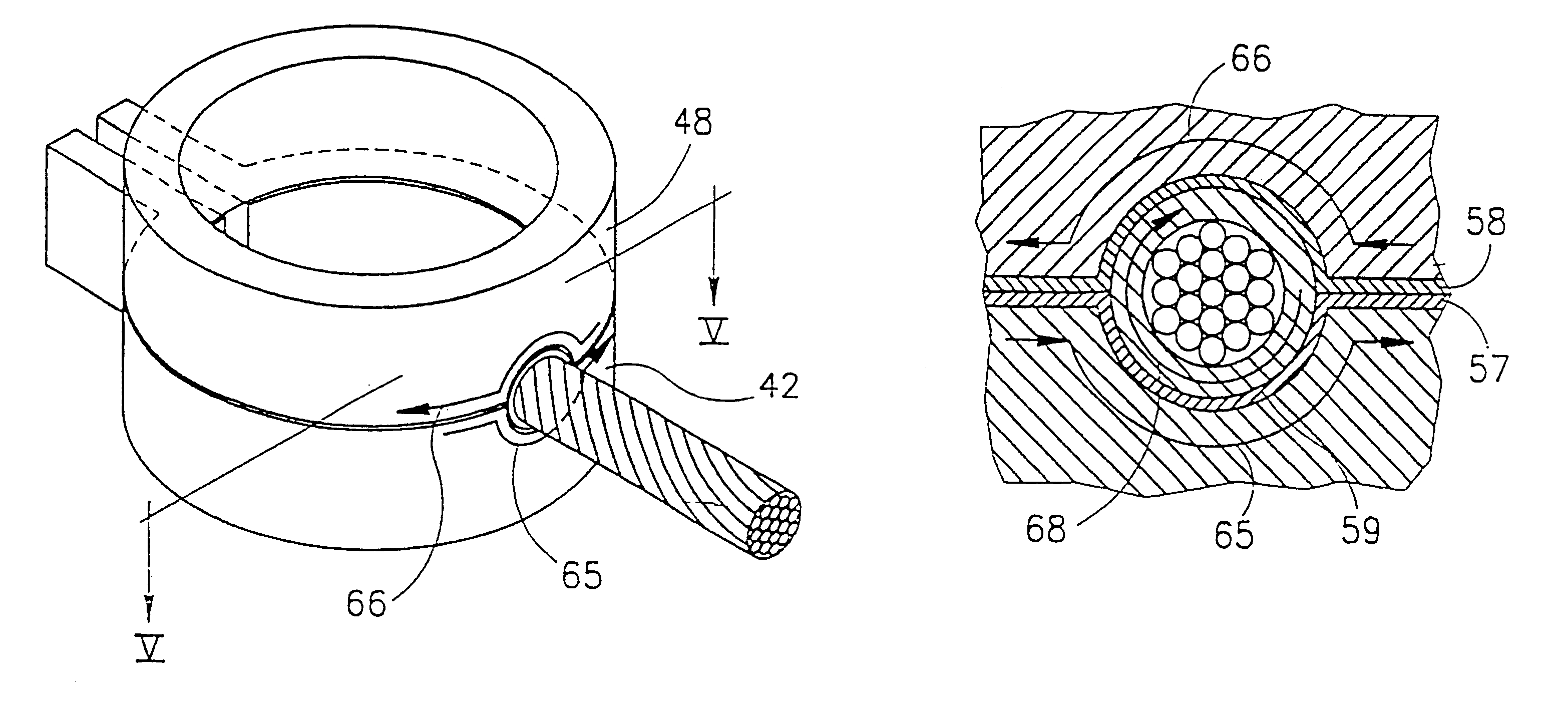
There are several aspects of the invention. In accordance with some aspects, the apparatus comprises a forming coil in direct contact with the electric discharge circuitry. In other aspects, the forming coil is in fact a secondary coil where current is induced by a primary coil which is in turn in direct electrical contact with an electrical discharge circuitry. The common feature in the apparatuses in accordance with all aspects of the invention is the fact that there is on the one hand, permanent electrical contact between the forming coil or the primary coil, as the case may be, and on the other hand, means are provided for easy placement of the tubular object to be formed in a forming space of the forming coil and extraction of the workpiece after forming.

Problems solved by technology

At times, however, the change in form results in the forced and rapid pressing of one workpiece against another which eventually results in either joining two workpieces together or welding both pieces, one to another.
The passing of a short duration high intensity electric current through the coil, gives rise to eddy currents in the metal workpiece, this in turn creating a magnetic pressure, resulting from the repulsive forces between the forming coil and the metal workpiece.
This however may create technical difficulties in a number of cases.
For example, in the case of joining of long steel pipes by a bridging sleeve, such as that described in U.S. Pat. No. 5,442,846, it is necessary to be able to open the coil to allow the sideways withdrawal of the pipes with the joining sleeve after joining (otherwise, it would have been necessary to extract the pipe by pulling it lengthwise, which is very often practically impossible).
However, the problem is that the planar portion of the lug is of a wider dimension than the diameter of the tubular portion and accordingly, if the forming coil would have been a standard fixed coil, it would have been practically impossible to extract the cable after forming.
However, the apparatuses disclosed in these U.S. patents are bulky and are not suitable for field use which is where the joining of the cable end and the cable lug takes place.
The problem is that the electric contact with the source has to be a very low resistance contact, and accordingly a bulky arrangement is required to ensure the maintenance of such a contact notwithstanding the fact that at least one of the two halves of the forming coil has to be displacable.

Method used


Image

  • Electromagnetic forming apparatus
  • Electromagnetic forming apparatus
  • Electromagnetic forming apparatus

Examples


Embodiment Construction

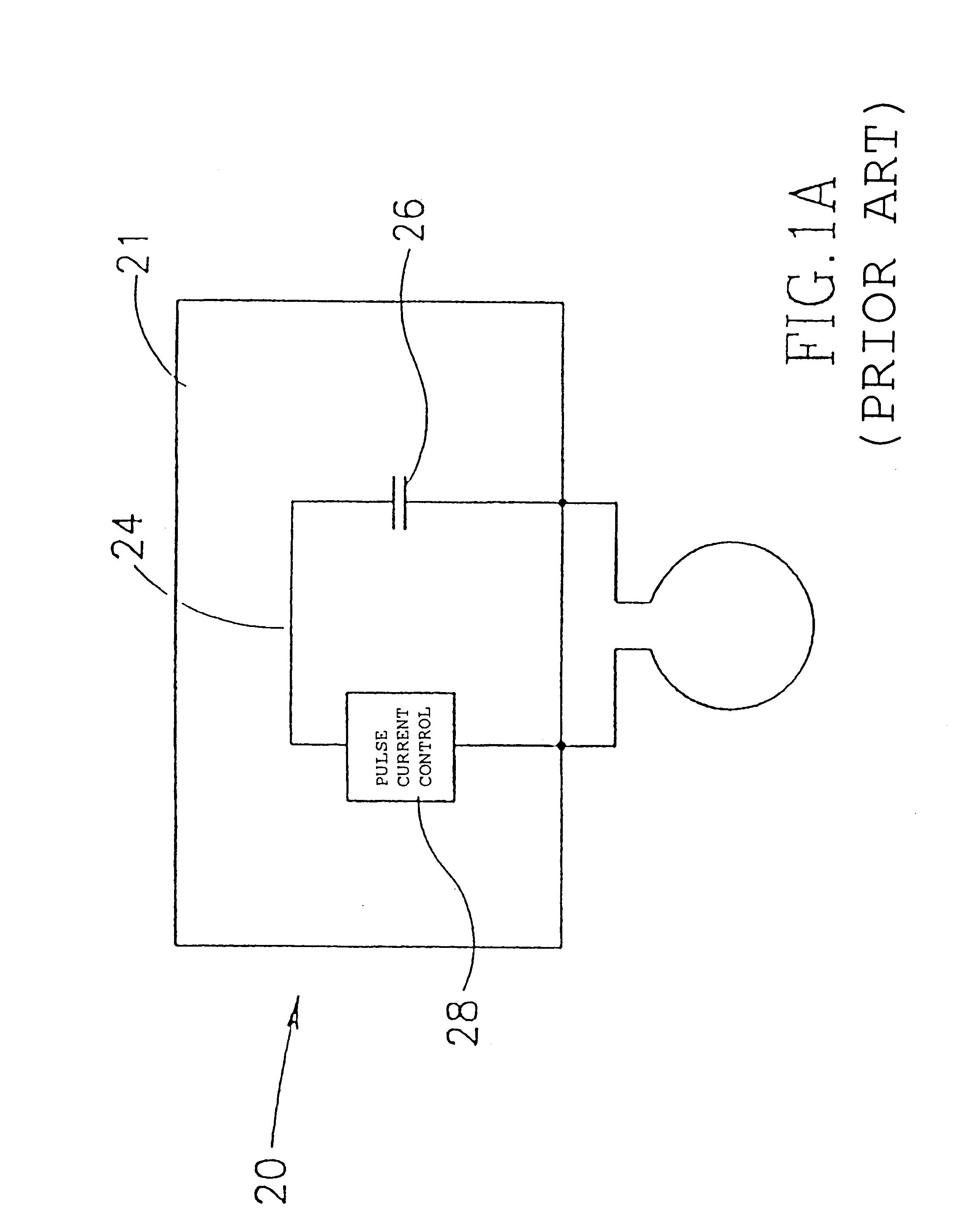
Reference is first being made to FIG. 1, showing schematic representations of two apparatuses of the invention. The apparatus generally designated 20 shown in FIG. I comprises an electric discharge unit 21 and a forming coil 22. Electric discharge unit 21 holds an electric discharge circuitry 24 comprising a discharge capacitor or bank of capacitors 26 and a pulse control module 28. In the embodiment of FIG. 1A, the forming coil 22 is in direct electric contact with the discharge circuitry 24.

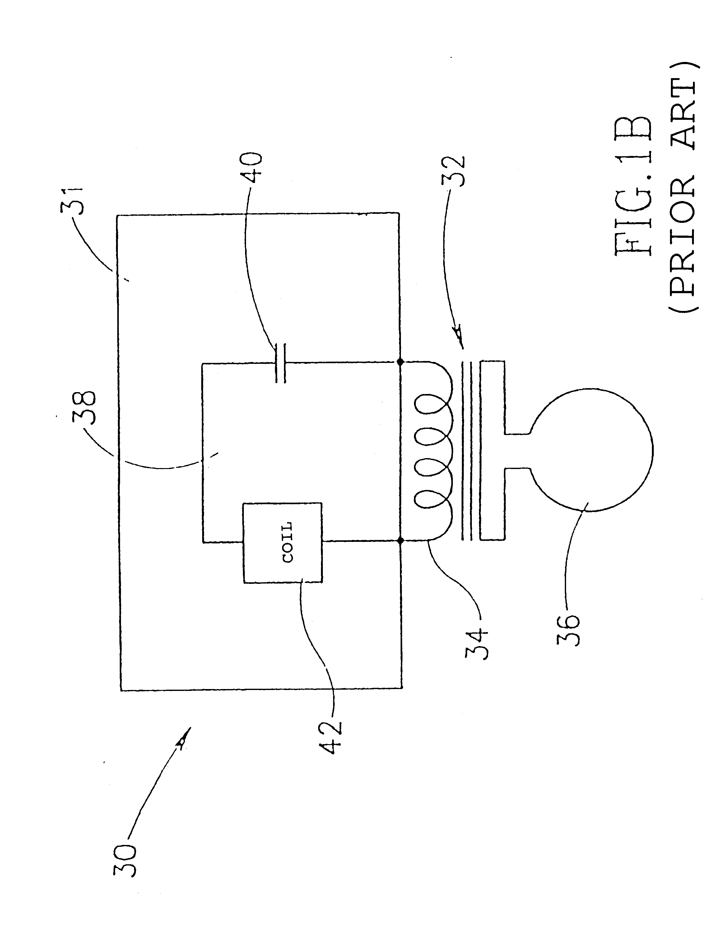
The apparatus shown in FIG. 1B, generally designated 30, comprises an electric discharge unit 31, a forming coil assembly 32 comprising a primary coil 34 and a secondary forming coil 36, the two coils being in an inductance relationship with one another. The primary coil 34 is in direct electric contact with an electric discharge circuitry 38 of electric discharge unit 30 which similarly as in the embodiment of FIG. 1A, comprises a capacitor or bank of capacitors 40 and a pulse control module 4...


PUM

PropertyMeasurementUnit
shapeaaaaaaaaaa
sizeaaaaaaaaaa
electrically insulatingaaaaaaaaaa

Abstract

A novel apparatus for pulse magnetic forming of a tubular workpiece is provided. The apparatus forms functionally a single wind coil and is particularly suitable for joining or welding of a tube onto another tube or a cylindrical object.

Description

The present invention is generally in the field of forming of metal objects by means of pulse magnetic force (PMF) forming. PMF forming are processes where a short duration magnetic pulse is used to change the form of a metal workpiece. Change in form may be an object by itself whereby the workpiece assumes a different form. At times, however, the change in form results in the forced and rapid pressing of one workpiece against another which eventually results in either joining two workpieces together or welding both pieces, one to another. (Joining is a process whereby the surfaces of two workpieces come into close association with one another, without a molecular interaction between the two surfaces, while welding is the process where the surfaces of the two workpieces in fact merge with one another, there being an interaction on the molecular level between the two surfaces). The term "forming" or "PMF forming" as used herein, will denote all such processes.PMF forming processes, p...

Claims


Application Information

Patent Timeline
Patent Type & Authority Patents(United States)
IPC IPC(8): B21D26/14B23K20/06B21D26/00
CPCB21D26/14B23K20/06H01R4/183H01R11/12
Inventor LIVSHIZ, YURIGAFRI, OREN
Owner INFINITY IP COMMERCIALIZATION ISRAEL LTD
Learn More