Robust signaling tone frequency measurement

Inactive Publication Date: 2001-05-08
LUCENT TECH INC
View PDF2 Cites 29 Cited by
  • Summary
  • Abstract
  • Description
  • Claims
  • Application Information

AI Technical Summary

Problems solved by technology

Because of the proximity of the CPE alerting signal to voice frequencies transmitted and received in typical telephone systems, reliable detection of the CPE alerting signal can sometimes be a problem in conventional CPEs.
This erroneous operation is often the result of harmonic components of speech signals occurring in the frequency ranges of a tone signal such as the standard CPE alerting si

Method used


Image

  • Robust signaling tone frequency measurement
  • Robust signaling tone frequency measurement
  • Robust signaling tone frequency measurement

Examples


Embodiment Construction

The present invention recognizes the performance versus cost limitations of current customer premise equipment (CPE), e.g., equipment capable of operation in a telephone system with combined call-waiting and caller identification (caller ID) services.

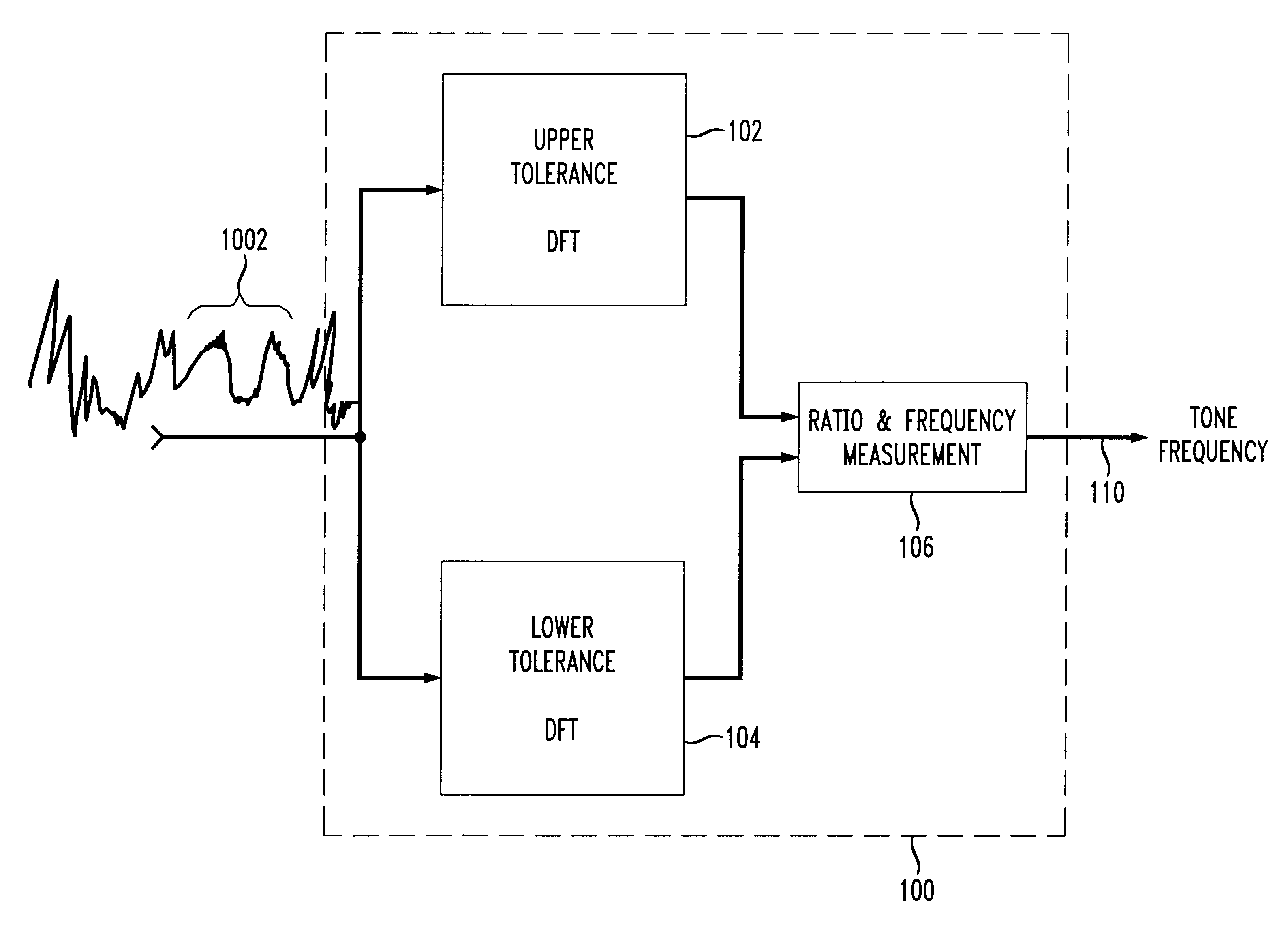
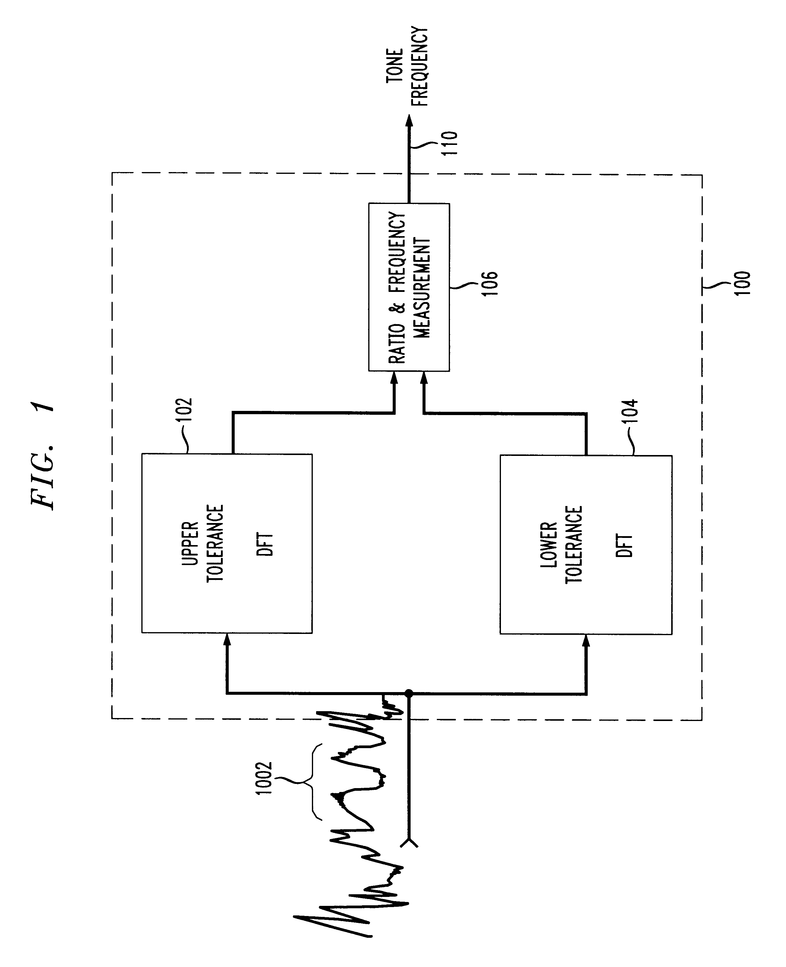
The present invention provides apparatus and methods for adaptively, reliably, and accurately measuring the frequency of an alerting or other signaling tone. An embodiment of a tone detector is described which is capable of measuring the frequency of a tone (continuous or pulsed) with a high degree of accuracy (e.g., to within 1 part in 10,000).

The present invention relates to a tone detector capable of high accuracy frequency measurement of an alerting or other signaling tone received over a telephone line. Conventional tone detectors require high order filters or a large, cumbersome Discrete Fourier Transform (DFT) algorithm to accurately measure the frequency of a tone signal. Most conventional tone detectors detect the presence of a...


PUM


Abstract

Apparatus and methods for adaptively, reliably, and accurately measuring the frequency of an alerting or other signaling tone. A tone detector measures the frequency of a tone (continuous or pulsed) with a high degree of accuracy (e.g., to within 1 part in 10,000). Two lower order or smaller DFTs measure the energy level in two separate but intersecting frequency ranges. A simple ratio is determined from the relative energy measured from discrete Fourier transforms relating to each of the two separate frequency ranges, and an actual measured frequency is determined.

Description

1. Field of the InventionThis invention relates generally to the measurement of alerting or other signaling tones. More particularly, it relates to a versatile method and apparatus capable of accurately measuring a frequency of an alerting or other tone even in an environment including speech signals.2. Background of Related ArtWhile the present invention relates to tone detection in general, it and its background are described with respect to a particular embodiment useful for detecting alerting tones relating to the reception of call related information, e.g., Caller ID information.As is well known, Caller ID services permit a telephone customer to learn the identity of, or at least the originating telephone number of, a party seeking to place a telephone call to the customer. An older service referred to as Call-Waiting (CW) alerts a customer engaged in a telephone connection to another party, that a third party desires to place a telephone call to the customer. A newer service o...

Claims


Application Information

Patent Timeline
IPC IPC(8): H04Q1/46H04Q1/30
CPCH04Q1/46
Inventor CANNON, JOSEPH M.JOHANSON, JAMES A.DAVIS, PAUL J.
Owner LUCENT TECH INC
Why Eureka
Try Eureka