

Electronic component mounting base board having heat slug with slits and projections
- Summary
- Abstract
- Description
- Claims
- Application Information
AI Technical Summary
Benefits of technology
Problems solved by technology
Method used
Image

Examples
first embodiment
the electronic component mounting base board according to the invention will be described below with reference to FIGS. 1-7.
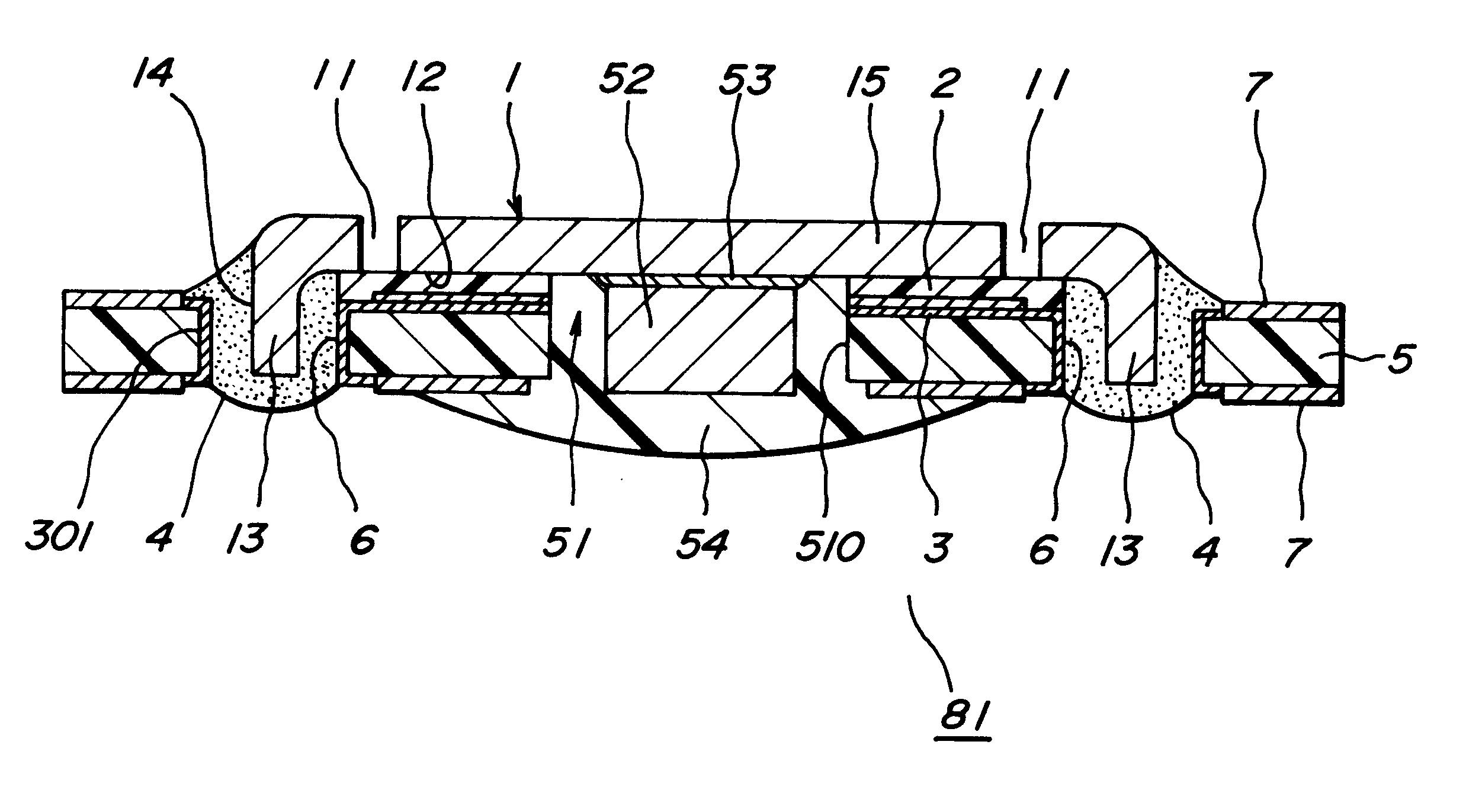
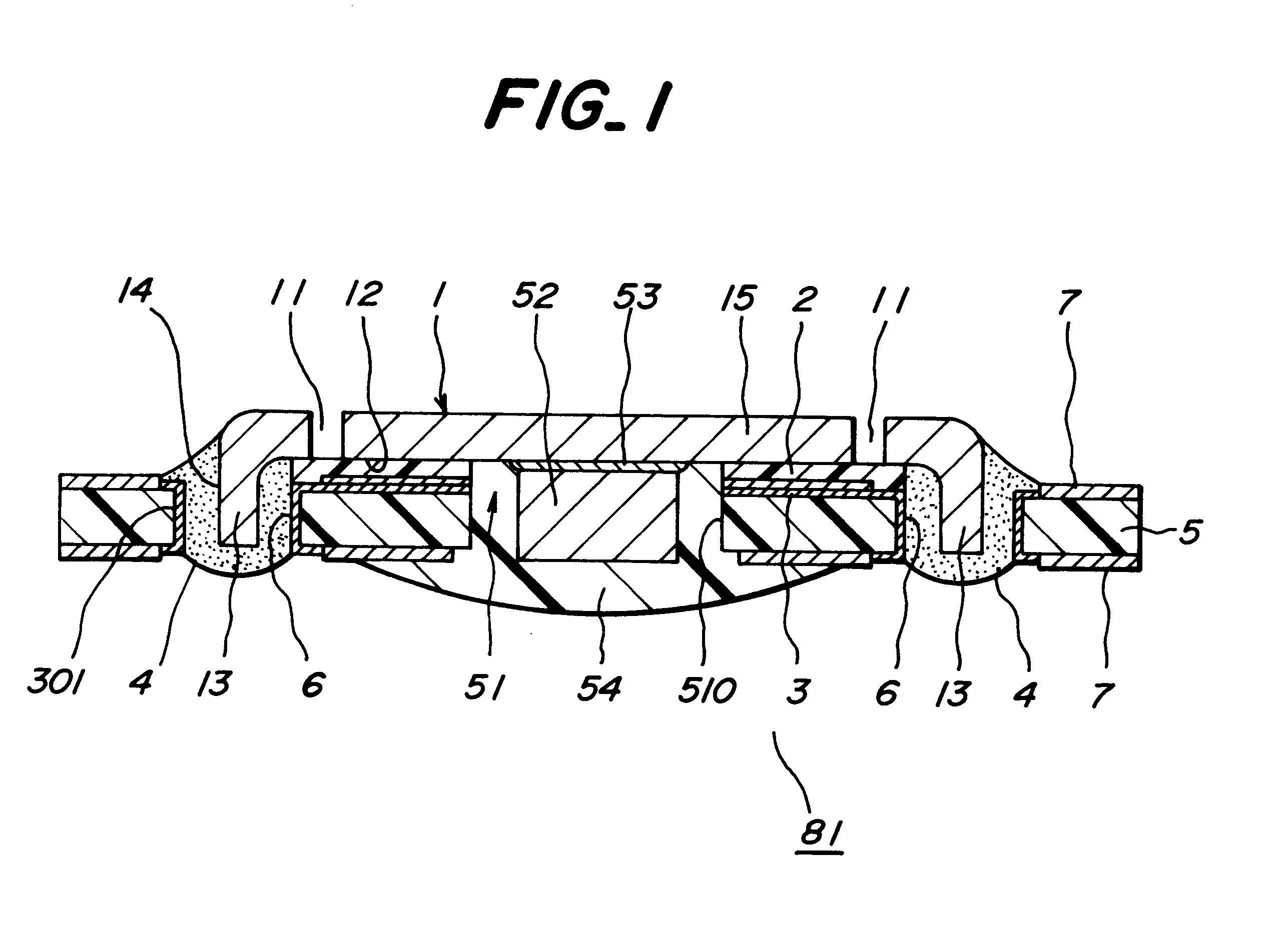
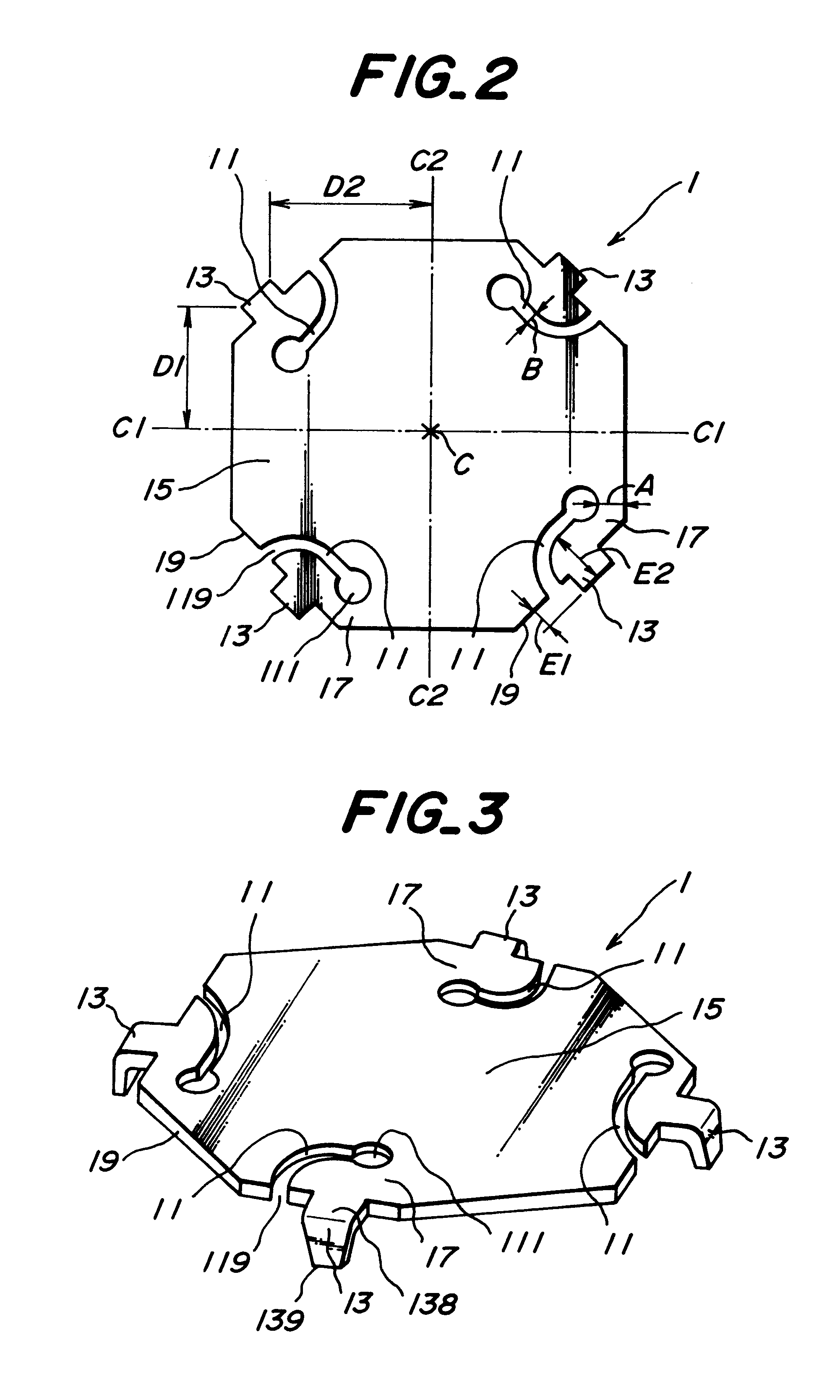
As shown in FIG. 1, the electronic component mounting base board 81 of this embodiment comprises an insulating substrate 5 provided with conductor circuits 3 and a mount portion 51 for an electronic component, and a heat slug 1 adhered to the insulating substrate 5. The heat slug 1 is comprised of a flat main body 15 arranged facing to the insulating substrate 5 and a projection portion 13 extending vertically from a side face 19 of the main body 15. The main body 15 is adhered to the insulating substrate 5 through a resin adhesive layer 2, while the projection portion 13 is inserted into a positioning hole 6 and joined to the insulating substrate 5 through a solder 4.
The heat slug 1 has a slit 11 absorbing deformation of the insulating substrate 5 between a resin-adhered region 12 of the main body 15 and a solder-joined region 14 of the projection portion 13. ...
second embodiment
the electronic component mounting base board according to the invention is shown in FIGS. 8 and 9, in which both end portions 111, 119 of the slit 112 are closed by the joint portion 17 connecting the resin-adhered region 12 to the solder-joined region 14.
As shown in FIG. 9, the minimum width A of the joint portion 17 is 0.15 mm, which is a half of thickness (0.3 mm) of the heat slug 1. The slit 112 is arranged in an elongated form in parallel to the side face 19 of the heat slug 1. Further, the projection portion 13 is connected to the positioning hole at a solder-joined region 14 adhered with the solder 4.
The other structure of the second embodiment is the same as the first embodiment.
In the second embodiment, both end portions 111, 119 of the slit 112 are closed by the joint portion 17 as shown in FIG. 8, so that the connection strength between the resin-adhered region 12 and the solder-joined region 14 becomes higher.
The same effects as in the first embodiment can be obtained ev...
third embodiment
the electronic component mounting base board (83) according to the invention is shown in FIGS. 10 and 11. As shown in FIG. 10, a slit 113 is formed in a projection portion 131 of the heat slug 1. The slit 113 is disposed along an extending direction of the projection portion 131.
The width K of the slit 113 is 0.5 mm, which is 55% of a width G (0.9 mm) of the projection portion 131. The projection portion 113 extends from the main body 15 of the heat slug 1 by 0.5 mm, in which a portion corresponding to a length H of 0.4 mm is folded downward.
The width of the slit 113 is favorable to be 30-99% of a width of a portion 138 adjacent to the main body of the heat slug 1. Thus, the strength of the heat slug can be increased. Moreover, the heat slug 1 has substantially the same octagonal form as in the first embodiment, in which four projection portions 131 are disposed on alternate sides.
As shown in FIG. 11, the projection portion 131 of the heat slug 1 is inserted into the positioning hol...
PUM
 Abstract
Description
Claims
Application Information