Apparatus for and method of processing billets in a rolling mill

a technology of rolling mill and equipment, which is applied in the direction of tensioning/braking arrangements, manufacturing tools, work heating devices, etc., can solve the problems of insufficient space on the rolling line, insufficient production time, and insufficient capital expenditures, and in most cases, prohibitive costs

Inactive Publication Date: 2001-05-22
MORGAN CONSTR CO
View PDF3 Cites 61 Cited by
  • Summary
  • Abstract
  • Description
  • Claims
  • Application Information

AI Technical Summary

Problems solved by technology

However, should the mill operator wish to decrease the cross section of the billet being rolled, there is insufficient space available on the rolling line to accommodate the additional roll stands needed to roll the larger cross sections d

Method used


Image

  • Apparatus for and method of processing billets in a rolling mill
  • Apparatus for and method of processing billets in a rolling mill
  • Apparatus for and method of processing billets in a rolling mill

Examples


Embodiment Construction

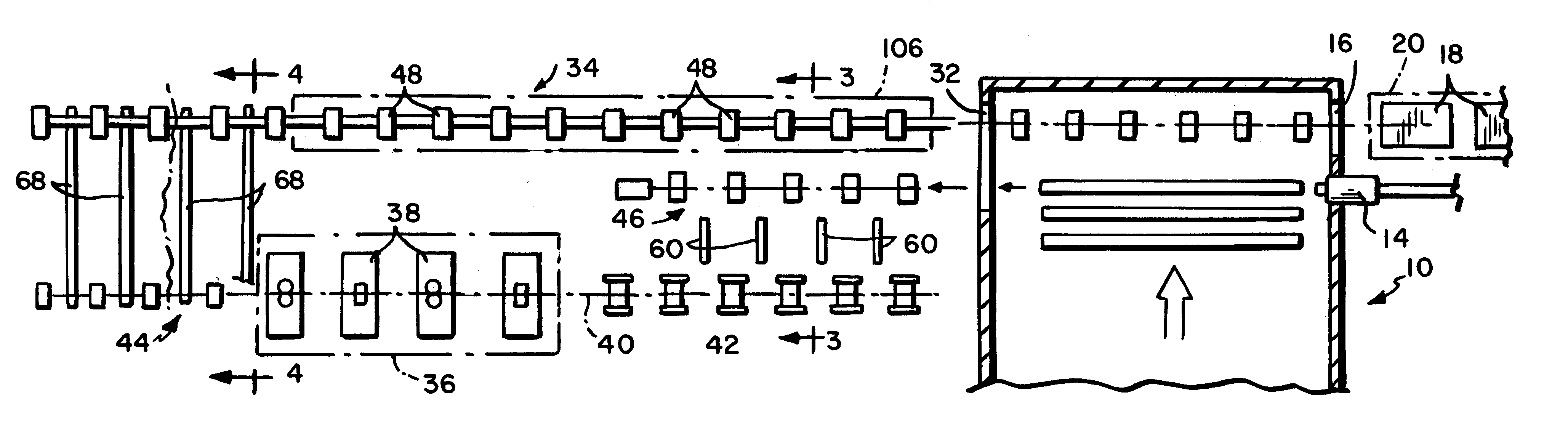
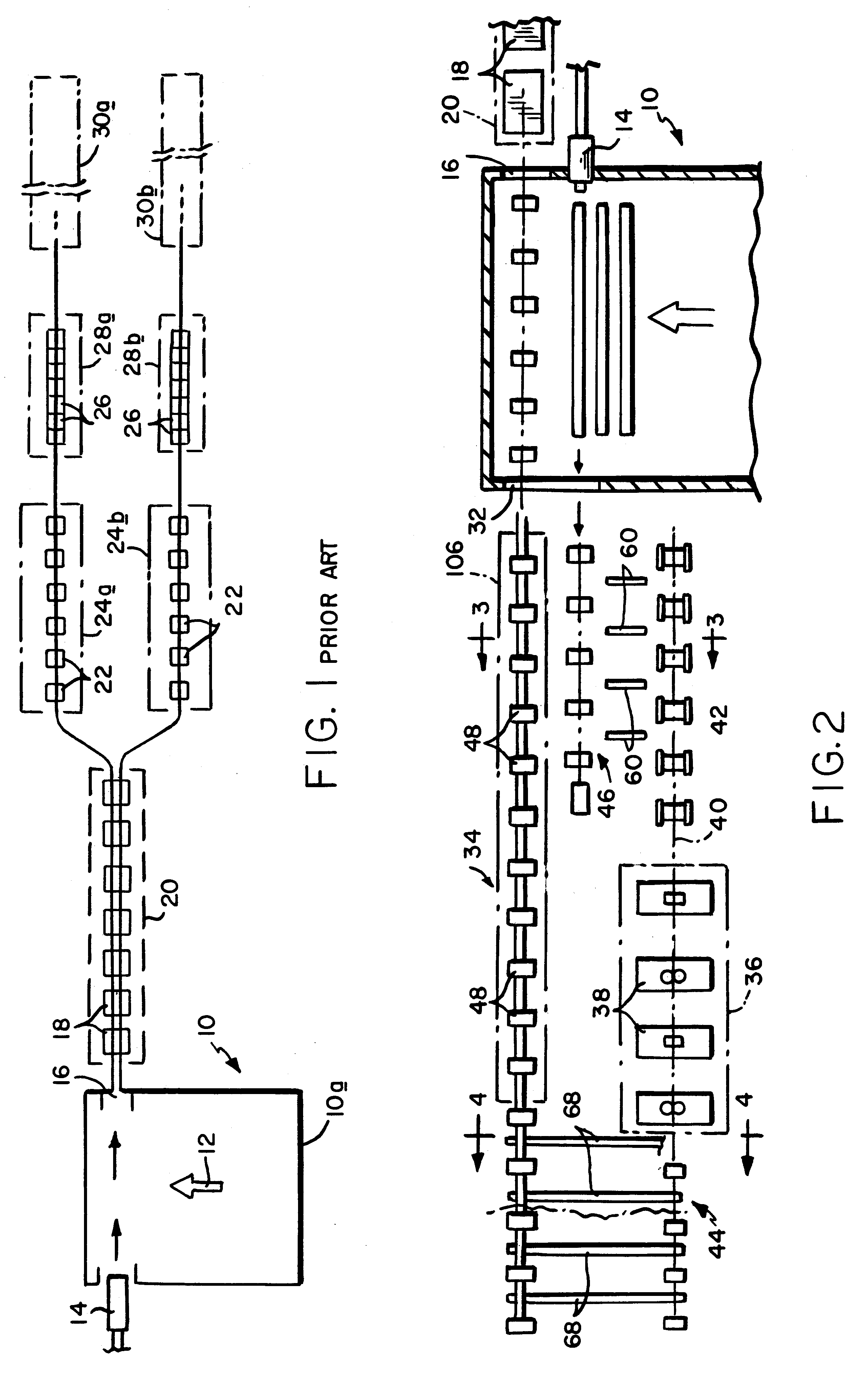
Referring initially to FIG. 1, a conventional rolling mill layout is shown comprising a billet reheating furnace 10 in which billets are loaded at an entry end 10a and transferred across the furnace in the direction indicated by arrow 12. In the course of being transferred across the furnace, the billets are heated to an elevated rolling temperature, typically above 1100.degree. C. A pushout mechanism 14 of conventional design then axially ejects the reheated billets through a first opening 16 in a first side of the furnace for rolling in the roll stands typically indicated at 18 of the roughing section 20 of the mill. The roughing section is capable of rolling two strands, which are then separated for continued rolling in the single strand roll stands typically indicated at 22 of intermediate sections 24a, 24b. Finish rolling occurs in the blocks 26 of finishing sections 28a and 28b. The finished products are then processed further in cooling lines 30a, 30b before being coiled or b...


PUM

PropertyMeasurementUnit
Temperatureaaaaaaaaaa
Areaaaaaaaaaaa

Abstract

A rolling mill has roughing, intermediate and finishing roll stands on a first side of a billet reheating furnace, and a breakdown mill on an opposite second side of the furnace. Billets are heated to an elevated rolling temperature in the furnace and are then ejected to the second side of the furnace for rolling in the breakdown mill before being directed back through the furnace for continued rolling into finished products at the first side of the furnace in the roughing, intermediate and finishing roll stands.

Description

1. Field of the InventionThis invention relates generally to rolling mills producing continuously hot rolled steel bars, rods and the like, and is concerned in particular with an improvement which enables existing mills to benefit from the cost savings associated with rolling larger billets, without necessitating either a relocation or a substantial reconfiguration of the billet reheating furnace.2. Description of the Prior ArtRod producers are now facing increasing demands for larger heavier rod coils and / or improved metallurgical properties throughout the entire cross section of the rod. Rolling longer billets will satisfy the first demand, but not the second. Rolling standard length billets with larger cross sections satisfies both demands.The resulting coils are larger and heavier, and the higher total reductions required to roll the larger billets down to rod sized will impart improved metallurgical properties uniformly from the surface to the center of the rods.In the conventi...

Claims


Application Information

Patent Timeline
IPC IPC(8): B21B39/02B21B39/00B21B45/00B21B39/12B21B1/00B21B1/02B21B1/16B21B1/46
CPCB21B1/026B21B39/004B21B39/12B21B45/004B21B45/008Y02P70/10B21B1/18
Inventor ROY, COLINSHORE, T. MICHAELPUCHOVSKY, MELICHER
Owner MORGAN CONSTR CO
Why Eureka
Try Eureka