Encapsulated thin-film resonator and fabrication method

a thin-film resonator and fabrication method technology, applied in piezoelectric/electrostrictive device details, piezoelectric/electrostrictive/magnetostrictive devices, piezoelectric/electrostriction/magnetostriction machines, etc., can solve the problems of poor overall performance, low q resonators, and failure to fabricate useful resonators by deposited piezoelectric layer of zinc oxide on aluminum substrates, q

Inactive Publication Date: 2001-05-29
QORVO US INC
View PDF3 Cites 50 Cited by
  • Summary
  • Abstract
  • Description
  • Claims
  • Application Information

AI Technical Summary

Benefits of technology

The present invention is a resonator and a method for fabricating the resonator that, in its preferred embodiment utilizes zinc oxide for the layer of piezoelectric material and that utilizes aluminum for the electrodes. A thin layer of aluminum nitride is deposited upon the aluminum electrode, which layer protects the surface of the aluminum electrode from oxydation and pins the surface of the aluminum electrode to prevent structural changes while, at the same time, providing a layer of material having a substantial degree of un

Problems solved by technology

However, in prior art devices, the gold, that was used as the electrodes and as the substrate for the zinc oxide, introduced excessive mechanical losses at UHF and microwave frequencies and which resulted in lower Q resonators and poorer overall performance as compared to devices that utilized a piezoelectric layer of aluminum nitride and aluminum electrodes.
Attempts to fabricate useful resonators by depositing a piezoelectric layer of zinc oxide upon an aluminum substrate were not successful because the process for depositing the zinc oxide utilized an oxygen rich environment, which oxydized the surface layer of the aluminum substrate during the initial film nucleation stage of the depo

Method used


Image

  • Encapsulated thin-film resonator and fabrication method
  • Encapsulated thin-film resonator and fabrication method
  • Encapsulated thin-film resonator and fabrication method

Examples


Embodiment Construction

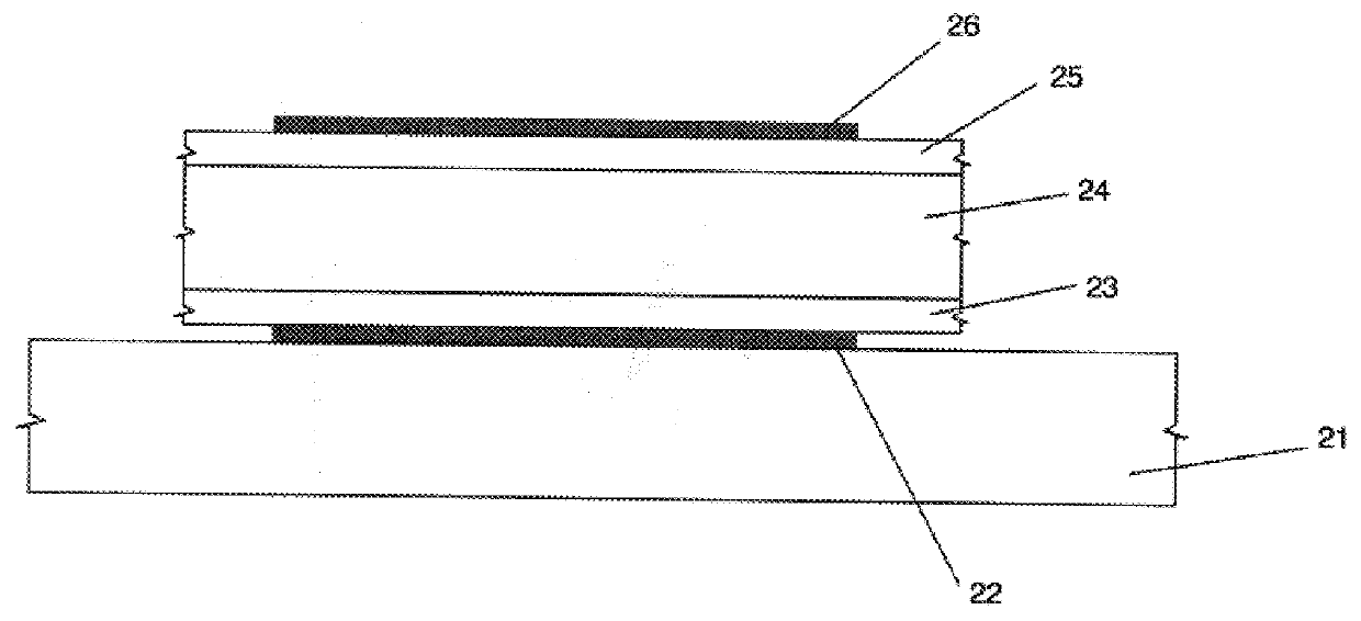
Referring to FIG. 2, a lower electrode 22 is fabricated by depositing aluminum or some other suitable conductor upon a substrate 21 by an evaporation or other deposition process that produces a layer of conducting material that has a substantial degree of uniformity in the orientations of the crystals within the conducting material. Portions of the layer of conducting material are then removed by etching or other means, so as to leave the desired pattern of conducting material as electrode 22. A barrier layer 23 of aluminum nitride or other suitable material is then deposited upon electrode 22 using an evaporation or other deposition process that produces a barrier layer 23 of material that also has a substantial degree of uniformity in the orientations of the crystals within the barrier layer. A piezoelectric layer 24 of zinc oxide or other suitable piezoelectric material is then deposited upon barrier layer 23.

Barrier layer 23 serves two important purposes. First, barrier layer 23...


PUM


Abstract

A thin-film piezoelectric resonator and method of fabrication that includes a barrier layer of material between the underlying electrode and a layer of piezoelectric material. For example, in a resonator that uses zinc oxide for the layer of piezoelectric material, a barrier layer of aluminum nitride is deposited upon an underlying aluminum electrode to protect the aluminum electrode from oxidation or structural deformation during the subsequent deposition of the piezoelectric layer of zinc oxide. The barrier layer of aluminum nitride is deposited in a manner so as to provide a substrate having a substantial degree of uniformity of crystal orientation upon which the layer of piezoelectric material may then be deposited in a manner such that the piezoelectric layer will, itself, also have a substantial degree of uniformity in the orientations of its crystals. The resonator includes a second electrode deposited upon the upper surface of the piezoelectric material or upon the upper surface of a second barrier layer of aluminum nitride that is deposited upon the upper surface of the piezoelectric layer.

Description

The invention described herein was made under or in the course of a contract with the U.S. Government.1. BACKGROUND OF THE INVENTIONa. Field of the InventionThis invention pertains to piezoelectric resonators and methods for the fabrication of piezoelectric resonators. More particularly, this invention pertains to thin film piezoelectric resonators and methods for fabricating thin film resonators.b. Description of the Prior ArtPiezoelectric resonators typically are used for the control of the frequency of oscillation of oscillators or as filters or components of filters that are used to select those frequency components of an electrical signal that lie within a desired band of frequencies while eliminating or attenuating those frequency components that lie outside the desired band of frequencies or that lie within specific undesired bands of frequencies.At ultra high (UHF) and microwave frequencies, piezoelectric resonators have been fabricated using thin-film techniques such as tho...

Claims


Application Information

Patent Timeline
IPC IPC(8): H03H3/02H03H9/17H03H3/00H03H9/00H03H9/02
CPCH03H3/02H03H9/02149H03H9/171H03H9/172
Inventor LAKIN, KENNETH MEADE
Owner QORVO US INC
Why Eureka
Try Eureka