Cutting insert having a chip former

a cutting insert and former technology, applied in the direction of turning machine accessories, metal working devices, turning machines, etc., can solve the problem of presenting a risk of damaging the generated surface, and achieve the effect of strong cutting and low cutting for

Inactive Publication Date: 2001-06-05
SECO TOOLS AB
View PDF5 Cites 45 Cited by
  • Summary
  • Abstract
  • Description
  • Claims
  • Application Information

AI Technical Summary

Benefits of technology

Another object of the present invention is to provide a cutting insert producing chips that do not damage the generated surface.
Another object of the present invention is to provide a cutting insert that produces low cutting forces.
Another object of the present invention is to provide a cutting insert with strong cutting corners.

Problems solved by technology

European Document A2-0 422 586 relates to a single sided cutting insert having an elliptical chip breaker which directs the chip in a desired direction while however presenting a risk of damaging the generated surface.

Method used


Image

  • Cutting insert having a chip former
  • Cutting insert having a chip former
  • Cutting insert having a chip former

Examples


Embodiment Construction

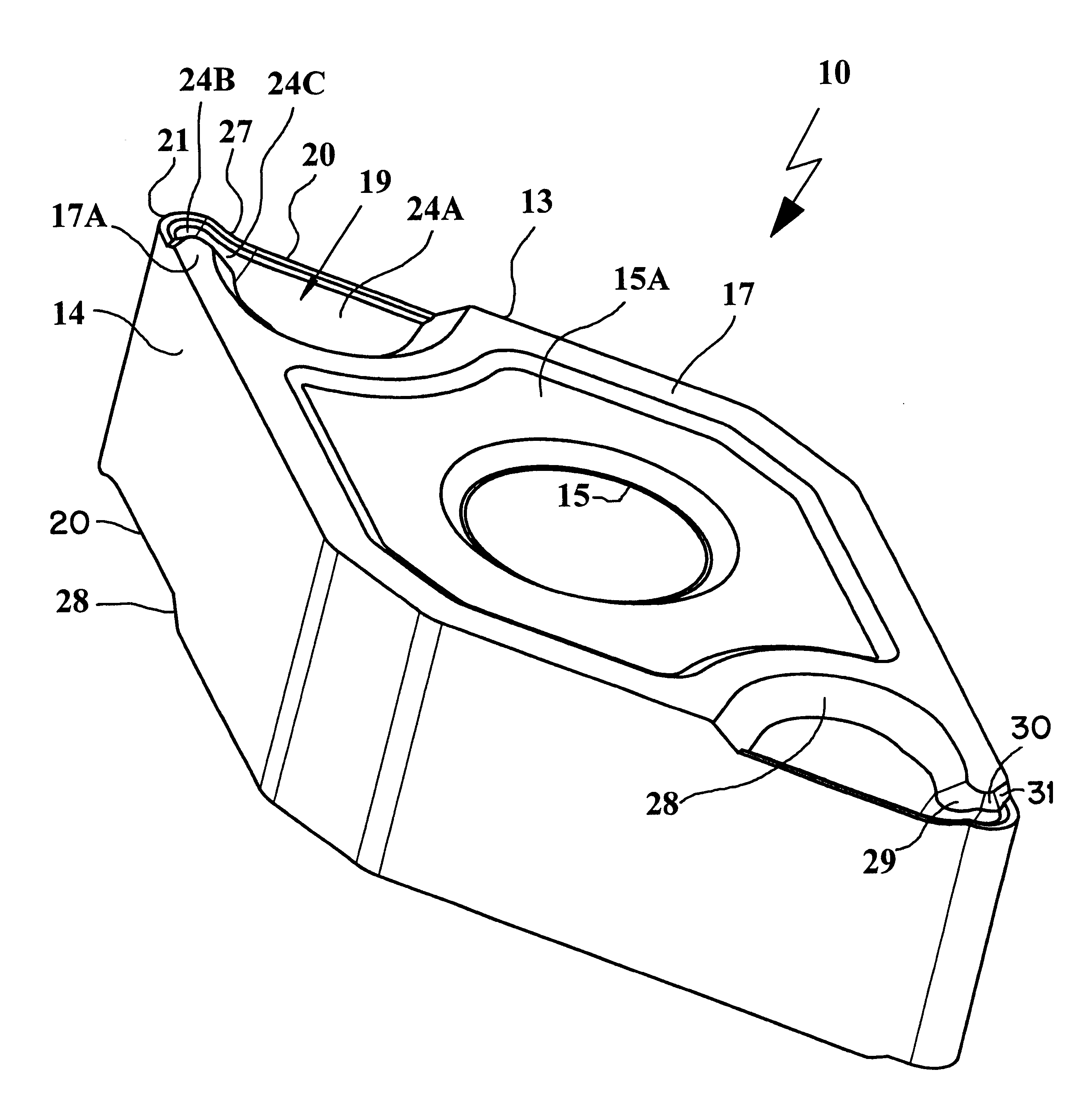
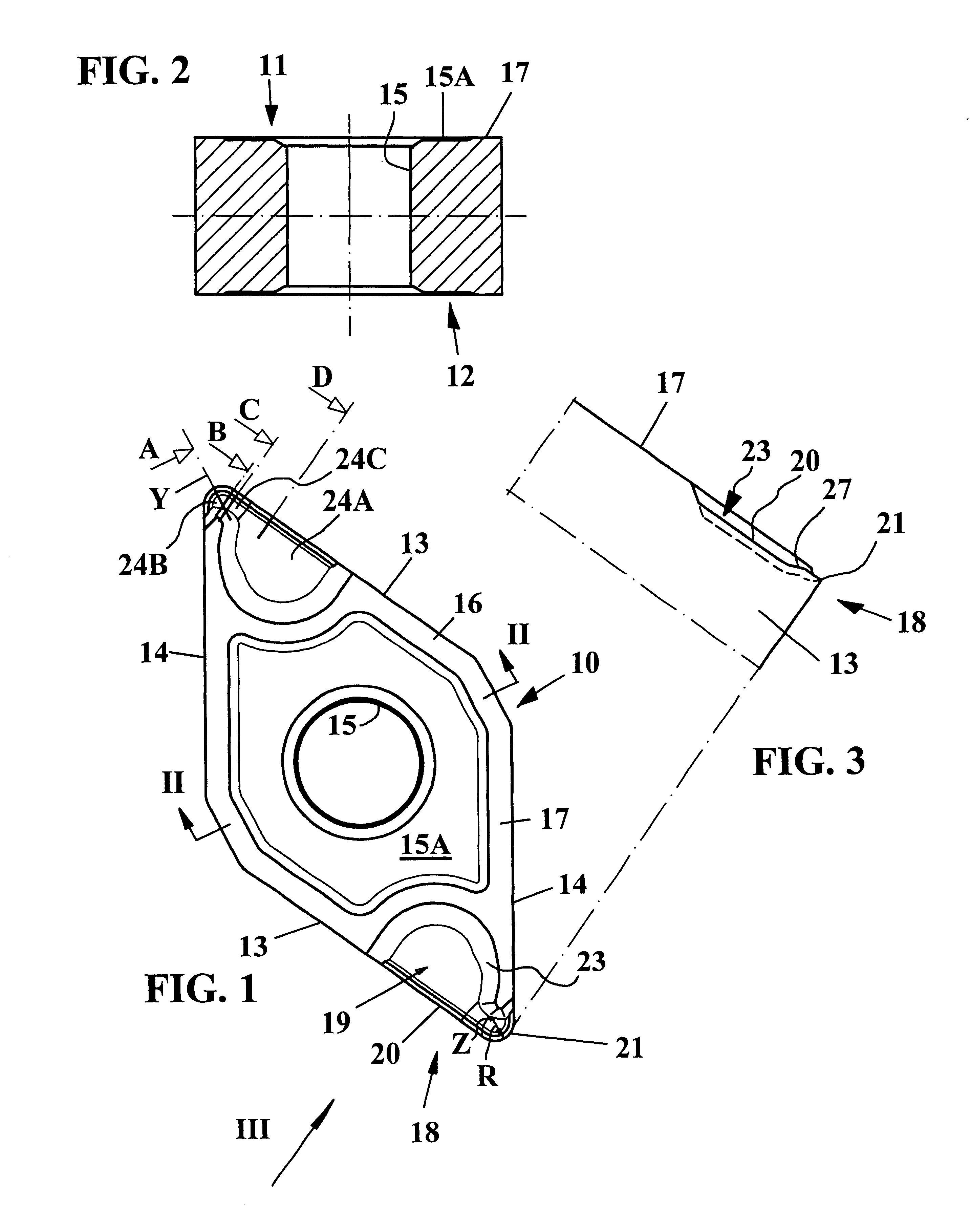
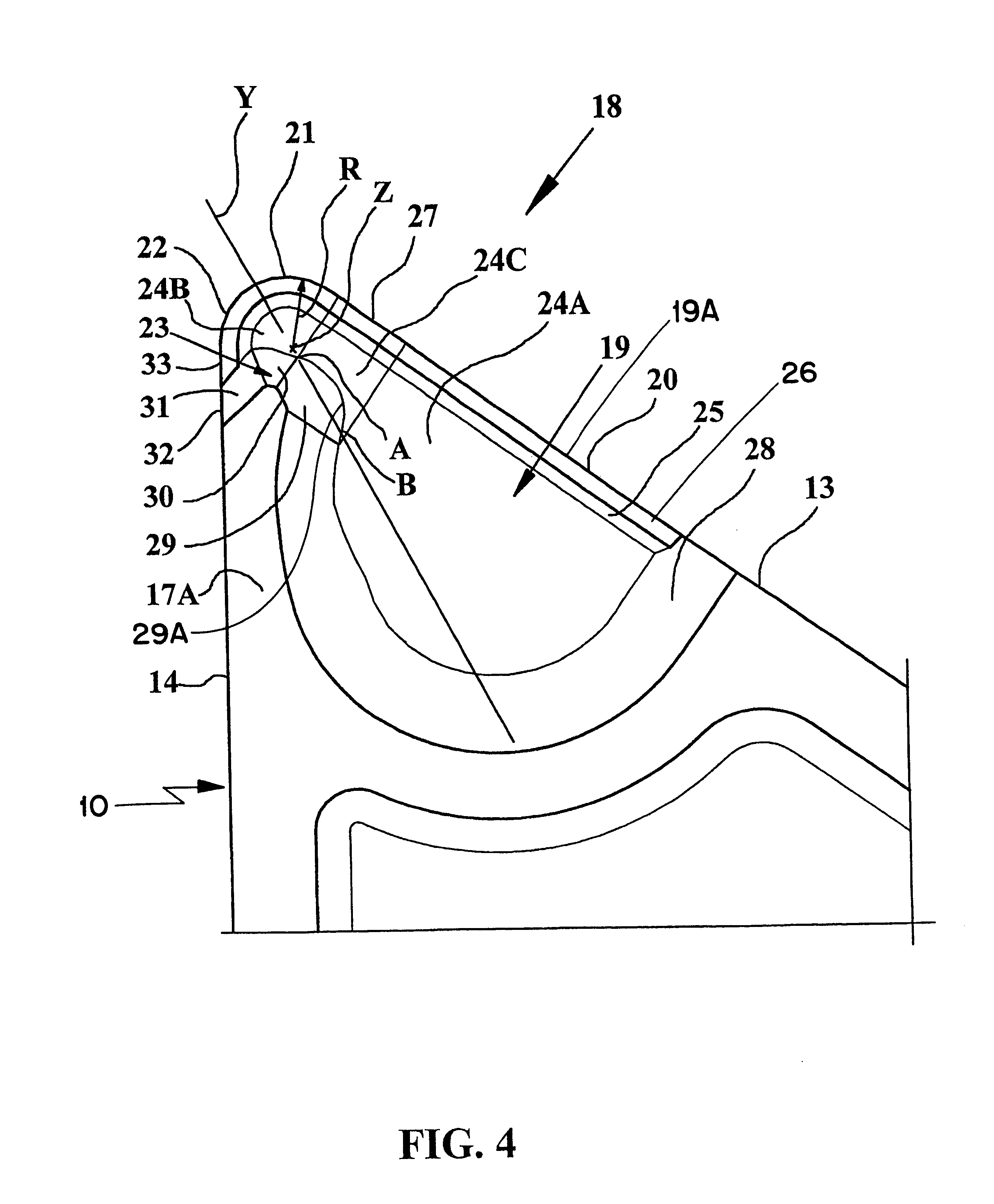
With reference to FIGS. 1-6, a double sided turning insert 10 according to the present invention is shown with a chip former or chip breaker 23, developed in order to be used mostly during internal turning of metallic workpieces. The cutting insert may of course be used also for external turning but then the advantage of the good chip control achieved by the insert becomes less important. The turning insert 10 has a polygonal body of hard wear resistant material such as cemented carbide, i.e., pressed and sintered tungsten carbide, or ceramics or similar. The body has an upper surface 11 and a lower surface 12 provided in separate, substantially parallel planes and several side surfaces 13, 14, each interconnecting said upper and lower surfaces 11, 12.

The side surface 13 constitutes a leading side surface in that it faces toward the direction of cutting F, whereas the side surface 14 constitutes a trailing side surface in that it faces away from the direction of cutting (see FIG. 7)...


PUM

PropertyMeasurementUnit
acute angleaaaaaaaaaa

Abstract

A turning insert, preferably for internal machining, includes a polygonal body of hard wear resistant material, which has an upper surface and a lower surface provided in separate substantially parallel planes and a number of side surfaces each interconnecting the upper and lower surfaces. A first side surface is a leading edge surface, and a second side surface is a trailing edge surface during machining. At least one chip former is provided. At least one rounded cutting corner having cutting edges is formed at an intersection of the two side surfaces. The cutting corner defines a bisector plane. The chip former is asymmetrically arranged relative to the bisector plane. The chip former has a surface that is provided in the plane of the upper surface. The surface is provided at substantially one side of the bisector plane and the convex portion of the chip former has a lower edge intersected by the bisector plane at least twice.

Description

The present invention relates to a turning insert for the cutting machining of metallic workpieces. More specifically the present invention relates to a turning insert with a chip former, developed foremost to be used for internal turning.PRIOR ARTSpecial demands are put on a metal cutting tool during turning of internal surfaces in comparison with external longitudinal turning. Such demands involve the need for low cutting forces due to long moment arms, and controlled chip forming in order not to damage the generated surface. European Document A2-0 422 586 relates to a single sided cutting insert having an elliptical chip breaker which directs the chip in a desired direction while however presenting a risk of damaging the generated surface. From U.S. Pat. No. 4,681,487 there is previously known a double-sided cutting insert for external turning having a chip breaker both for fine and rough turning.OBJECTS AND SUMMARY OF THE INVENTIONOne object of the present invention is to provid...

Claims


Application Information

Patent Timeline
Patent Type & Authority Patents(United States)
IPC IPC(8): B23B27/14B23B27/22
CPCB23B27/143Y10T407/235Y10T407/245Y10T407/24
Inventor NORSTROM, THOMAS
Owner SECO TOOLS AB
Why Eureka
Try Eureka