This helps you quickly interpret patents by identifying the three key elements:
Problems solved by technology
Method used
Benefits of technology
Problems solved by technology
However, in the case of quadrature modulation in which the in-phase axis and quadrature axis baseband signal waveform to be read out must be determined based on both inphase and quadrature components of the coordinates of the signal point corresponding to the transmission data, for example, in the .pi. / 4 shift QPSK and in the PSK-VP (phase shift keying with varied phase) system described in Pages 412-419 of the proceedings of the 40th IEEE Vehicular Technology Conference), it is impossible to extract the in-phase component and quadrature component data independently at the in-phase axis and quadrature axis for each time slot and form a data pattern.
Method used
Image
Click on the blue label to locate the original text in one second.
Reading with bidirectional positioning of images and text.
Examples
fourth embodiment
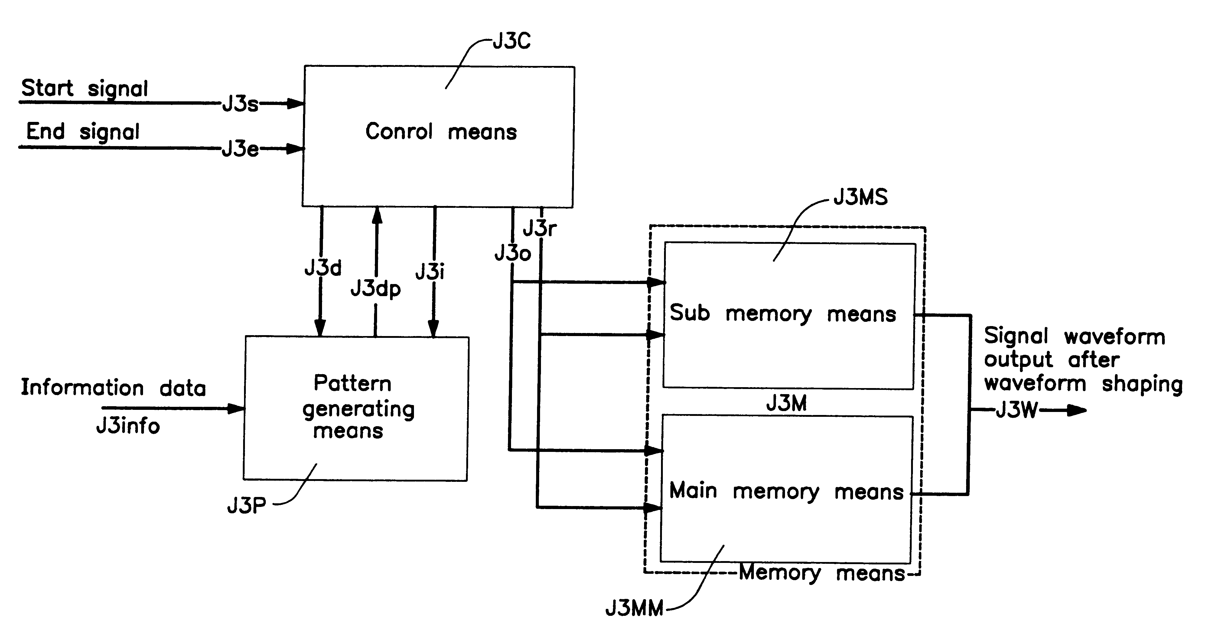
FIG. 15 is a schematicblock diagram illustrating basic configuration of the first, second, third, and fourth embodiment of the waveform shaping equipment according to the present invention.
To the input of the pattern generator J3P, information data J3info is successively inputted from outside of the waveform shaping equipment, and at the pattern generator J3P, dummy data J3d generated from the control means J3c is added to the head and the trail of the information data string J3info to form a packet with dummy data, and part of the packet with dummy data is extracted to generate the data pattern J3dp. To the control means J3C, the transmission status signal which advises the presence of information data J3info is inputted from outside of the waveform shaping equipment as start signal J3s and end signal J3e. The start signal J3s is a signal to input the pulse wave for triggering as soon as the head of the information data J3info is inputted and the end signal J3e is a signal to inpu...
first embodiment
Now, the specific description will be made on the generation timing of the input control signals, output control signals, and readout signals from the comparing unit in the case of this
In this first embodiment, D (k) (k=1, . . . , n) denotes the information data. Each 1T, 2T, . . . , (n+14)T shows the elapsed time for every unit time T, and A (1), A (2), . . . , A (5) denote each time slot in the pattern, respectively. Now, the present time slot is A (3). In this first embodiment, the number of shifts of the delay unit is designated asK=4 and the number of shifts of the shift register as L=9.
Observation of the time sequence shown in FIG. 18 indicates that time 1T to 5T and time (n+10)T to (n+14)T coincide with the spare sequence containing data value 0 and time 6T to (n+9)T with the ordinary sequence comprising binary values of 1 and -1. In the period from time 2T to 5T, the dummy data corresponding to the predummy data is generated from the dummy data generator, while in the period...
second embodiment
Now, the specific description will be made on the generation timing of the input control signals, output control signals, and readout signals from the comparing unit in the case of this
In this second embodiment, D (k) (k=1, . . . , n) denotes the information data. Each 1T, 2T, . . . , (n+10)T shows the elapsed time for every unit time T, and A (1), A (2), . . . , A (5) denote each time slot in the pattern, respectively. Now, the present time slot is A (3). In this second embodiment, the number of shifts of the delay unit is designated as K=2 and the number of shifts of the shift register as L=7.
Observation of the time sequence shown in FIG. 19 indicates that time 1T to 5T and time (n+6)T to (n+10)T coincide with the spare sequence containing data value 0 and time 6T to (n+9)T with the ordinary sequence comprising binary values of 1 and -1. In the period from time 2T to 3T, the dummy data corresponding to the predummy data is generated from the dummy data generator, while in the peri...
PUM
Abstract
In the transmitter which carries out burst transmission using information data as a packet, if the status is divided into four modes, namely, burst stop mode, burst rising mode, burst continuous mode, and burst falling mode, a waveform shaping equipment designed to read out shaped waveform data for each mode from outputs of either of the two memory tables, the first memory table which holds waveform data for specific data patterns used in common in burst rising mode and burst falling mode and the second memory table which holds waveform data for all data patterns used in the burst continuous mode, or a waveform shaping equipment comprising the third memory table which holds waveform data corresponding to all the data patterns used in the burst rising mode and the fourth memory table which holds waveform data corresponding to all data patterns used in the burst falling mode and generating shaped waveform data by synthesizing the two outputs of the third and the fourth memory tables at the time of burst continuous mode.
Description
1. Field of the InventionThe present invention relates to the waveform shaping equipment and waveform-shaping method for generating bandlimited signals, and for preventing band spread at the head and trail at the edge of burst when burst-like data string is transmitted in the data transmission in which data is transmitted in the form of packet.2. Related Art of the InventionIn the radio communication, etc., when a packet comprising transmission data is transmitted, it is necessary to limit the bandwidth (bandlimitation) to prevent adjacent channel interference for effective utilization of frequency. For bandlimitation of signals, it is common to limit the bandwidth with respect to the signal waveform of the baseband. Two systems are available for band-limiting the basebandsignal waveform: an analog system using analog filter and a digital system by digital signalprocessing. One of the digital systems is the method to shape waveform by reading out and concatenating the baseband sig...
Claims
Application Information
Patent Timeline
Application Date:The date an application was filed.
Publication Date:The date a patent or application was officially published.
First Publication Date:The earliest publication date of a patent with the same application number.
Issue Date:Publication date of the patent grant document.
PCT Entry Date:The Entry date of PCT National Phase.
Estimated Expiry Date:The statutory expiry date of a patent right according to the Patent Law, and it is the longest term of protection that the patent right can achieve without the termination of the patent right due to other reasons(Term extension factor has been taken into account ).
Invalid Date:Actual expiry date is based on effective date or publication date of legal transaction data of invalid patent.

