Fuel system and arrangement for small watercraft

a fuel system and small watercraft technology, applied in the engine field, can solve the problems of shortening the useful affecting the performance of the fuel pump, and affecting the service life of the fuel pump

Inactive Publication Date: 2001-06-12
YAMAHA MOTOR CO LTD
View PDF13 Cites 24 Cited by
  • Summary
  • Abstract
  • Description
  • Claims
  • Application Information

AI Technical Summary

Problems solved by technology

One problem with this arrangement is that hot exhaust gases flowing through the exhaust system may be routed very close to other components of the engine, damaging them or resulting in their poor performance.
This is true for the fuel pump where the heat from the exhaust system may damage the fuel pump or shorten its useful life.
Such watercraft, however, sacrifice the handling performance of the w

Method used


Image

  • Fuel system and arrangement for small watercraft
  • Fuel system and arrangement for small watercraft
  • Fuel system and arrangement for small watercraft

Examples


Embodiment Construction

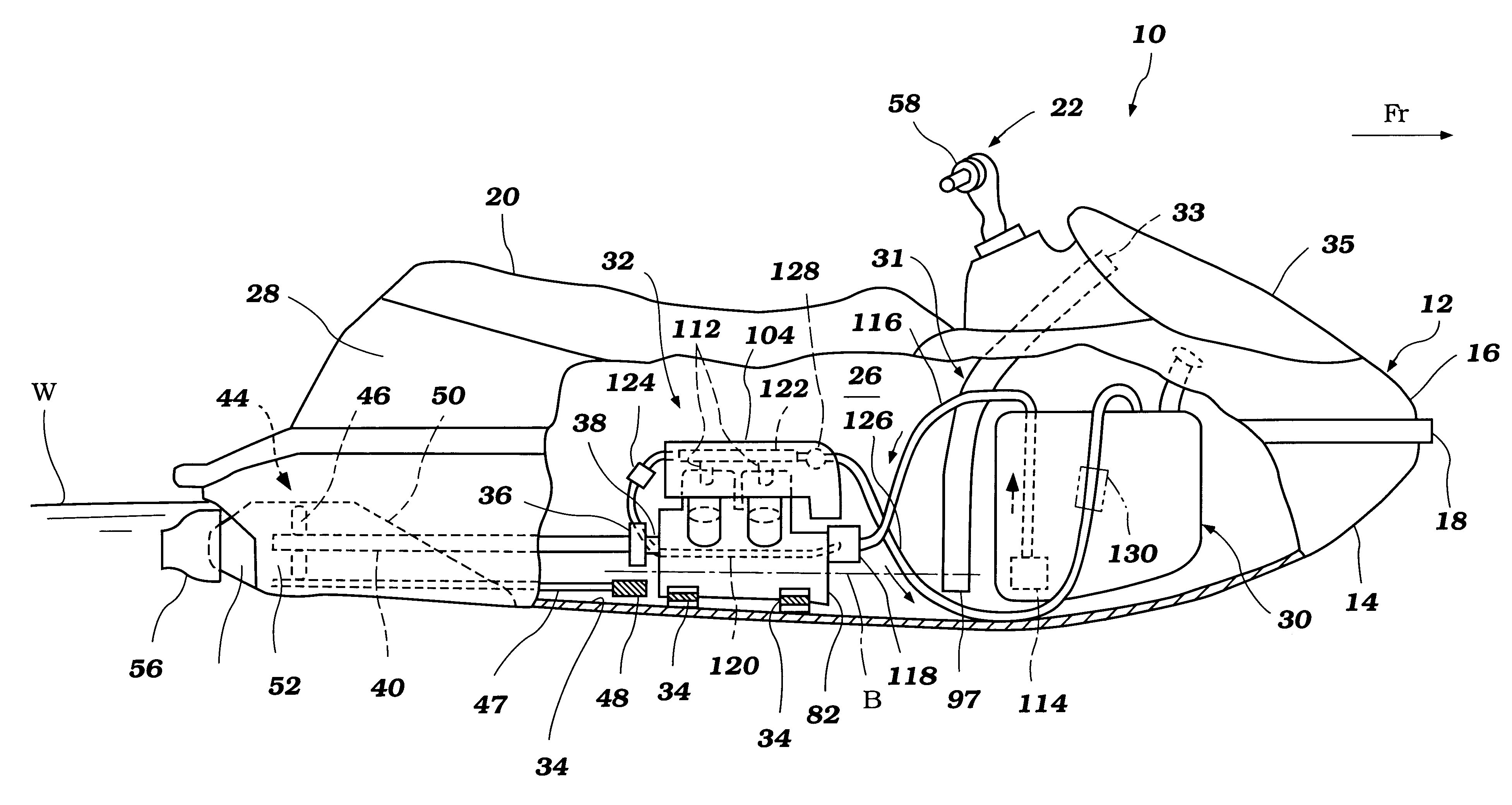
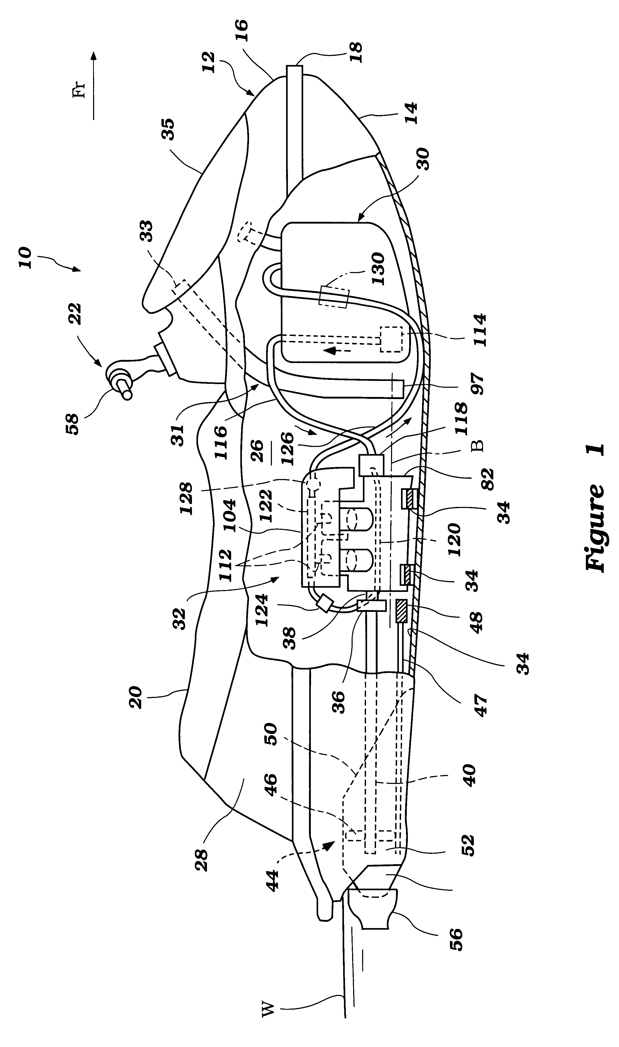
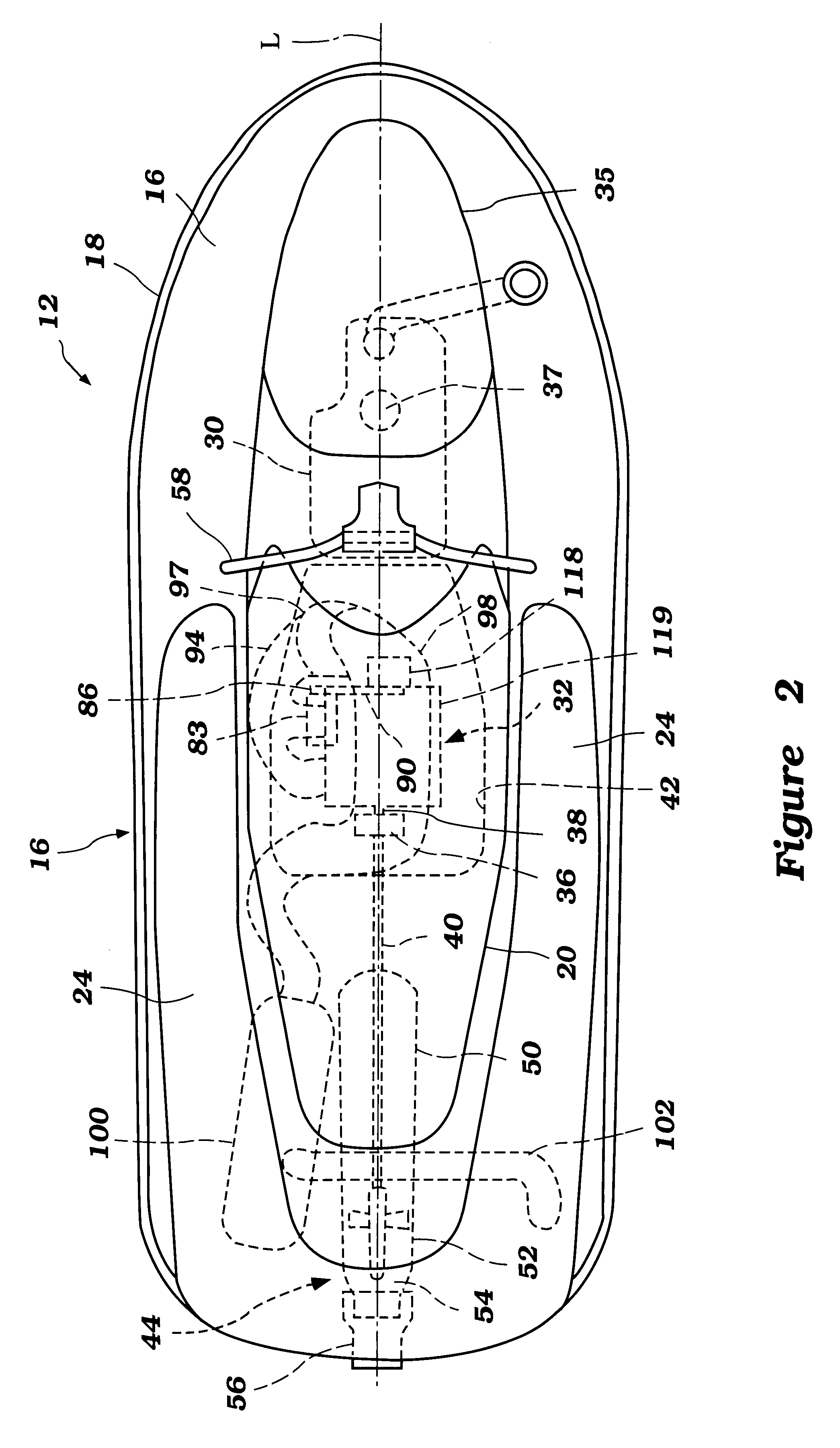
The present fuel supply system and its arrangement on an engine have particular utility for use with personal watercraft, and thus, the following describes the fuel supply system in the context of a personal watercraft. This environment of use, however, is merely exemplary. The present fuel supply system can be readily adapted by those skilled in the art for use with other types of marine engines as well, such as, for example, but without limitation, small jet boats and the like. The fuel supply system may also be adapted for use with internal combustion engines that are used in other applications.

Before describing the present fuel supply system, an exemplary personal watercraft 10 will first be described in general details to assist the reader's understanding of the environment of use and the operation of the exhaust system. The watercraft 10 is suited for movement through a body of water W in a direction Fr (toward a front end or bow of the watercraft).

As illustrated in FIGS. 1 an...


PUM


Abstract

A small watercraft includes an improved fuel supply system that is configured and arranged to provide a compact engine design while promoting air cooling of at least a portion of the fuel supply system. In one mode, a fuel pump of the system is at least partially located within an air flow path between an outlet of an air duct and an inlet of the engine induction system. The air flow cools the fuel pump to reduce its operating temperature. As a result, the durability and performance of the fuel pump is improved despite the fuel pump lying in close proximity to the engine's exhaust system. Shock-absorbent mounts also couple at least a portion of the fuel supply system (e.g., the fuel pump and a fuel delivery rail) to the hull of the watercraft. These fuel system components consequently experience lessened impact when the watercraft skips over the body of water on which it is planing, and are thus less susceptible to breakage.

Description

1. Field of the InventionThe present invention relates in general to an engine, and in particular to a fuel system and arrangement for a marine engine.2. Description of Related ArtPersonal watercraft have become popular in recent years. This type of watercraft is sporty in nature; it turns swiftly, is easily maneuverable, and accelerates quickly. Personal watercraft today commonly carry one rider and one or two passengers.A relatively small hull of the personal watercraft commonly defines a rider's area above an engine compartment. An internal combustion engine frequently powers a jet propulsion unit which propels the watercraft. A plurality of engine mounts support the engine within the engine compartment in front of a tunnel formed on the underside of the watercraft. The jet propulsion unit is located within the tunnel and is driven by a drive shaft connected to the engine.Personal watercraft often employ an inline, multi-cylinder, crankcase compression, two-cycle engine. The engi...

Claims


Application Information

Patent Timeline
IPC IPC(8): F02M31/00F02M31/20F02M37/00F02M37/20B63B35/73F02B61/00F02B61/04F02M35/00F02M35/16
CPCF02M31/20F02M35/1019F02M35/167F02M37/007F02M37/0088F02M37/20F02M35/1233B63B35/731B63B2770/00F02B61/045F02M35/12Y02T10/126B63H21/14B63H21/24B63H21/38B63B34/10Y02T10/12
Inventor OZAWA, SHIGEYUKI
Owner YAMAHA MOTOR CO LTD
Why Eureka
Try Eureka