
Combination sheath and catheter for cardiovascular use

a catheter and sheath technology, applied in catheters, infusion syringes, surgery, etc., can solve the problems of insufficient introduction of contrast agents, tissue damage, and the sheath itself may not serve as the conduit, etc., and achieve the effect of relatively easy manufacturing and low cos

Inactive Publication Date: 2001-06-12
STRATIENKO ALEXANDER ANDREW
View PDF16 Cites 231 Cited by
  • Summary
  • Abstract
  • Description
  • Claims
  • Application Information

AI Technical Summary

Benefits of technology

Accordingly, it is an object of the invention claimed herein to provide a vascular interventional device that may be manufactured relatively easily and inexpensively. It is also an object of the invention to provide such a device which may be used to deliver a fluid agent to a target vessel or vessel segment at a clinically effective rate. Another object of the invention is to provide such a device that may also be used to deliver a second interventional device to a target vessel or vessel segment, which device may be used for therapeutic or diagnostic purposes while the fluid agent is being delivered at a clinically effective rate. It is yet another object of the invention to provide such a device that is adapted to selectively engage a target vessel of the cardiovascular system of a patient. It is still another object of the invention to provide a method for treating or studying a cardiovascular condition of a patient. It is yet another object of the invention to provide a method to measure the difference in blood pressure (if any) across a vascular segment of the cardiovascular system of a patient.

Problems solved by technology

In most cases, the sheath itself may not serve as the conduit for delivery of contrast agent because conventional sheaths are usually quite short and are not adapted to selectively engage a vessel of the cardiovascular system.
Furthermore, conventional sheaths have only a single end hole, and fluid injected therethrough in volumes sufficient for a contrast agent would likely flow from the end hole at such a velocity that tissue damage might occur.
These devices operate to deliver fluid to a target point within a vessel at low flow rates that are useful for introduction of pharmacological agents such as thrombolytic drugs, but are wholly insufficient for proper introduction of a contrast agent.
Furthermore, these devices do not accommodate or facilitate the introduction of a second interventional device into the cardiovascular system of a patient.
However, since it is sized to function as a guidewire too, it may only be used to disperse fluid at the target location at a very low rate, thereby limiting its use to the delivery of drugs only.
Many of the known infusion guidewires include complicated multi-lumenal structures and valve arrangements that are difficult and expensive to manufacture.
Furthermore, these devices generally operate to deliver fluid agents to a target site at low flow rates that are wholly insufficient for use in delivering contrast media.
However, when the Ginsburg device is used to deliver a significant volume of contrast fluid in order to displace blood volume, the velocity of delivery of contrast fluid out the end hole may be so great that tissue damage may occur.

Method used


Image

  • Combination sheath and catheter for cardiovascular use
  • Combination sheath and catheter for cardiovascular use
  • Combination sheath and catheter for cardiovascular use

Examples


second embodiment

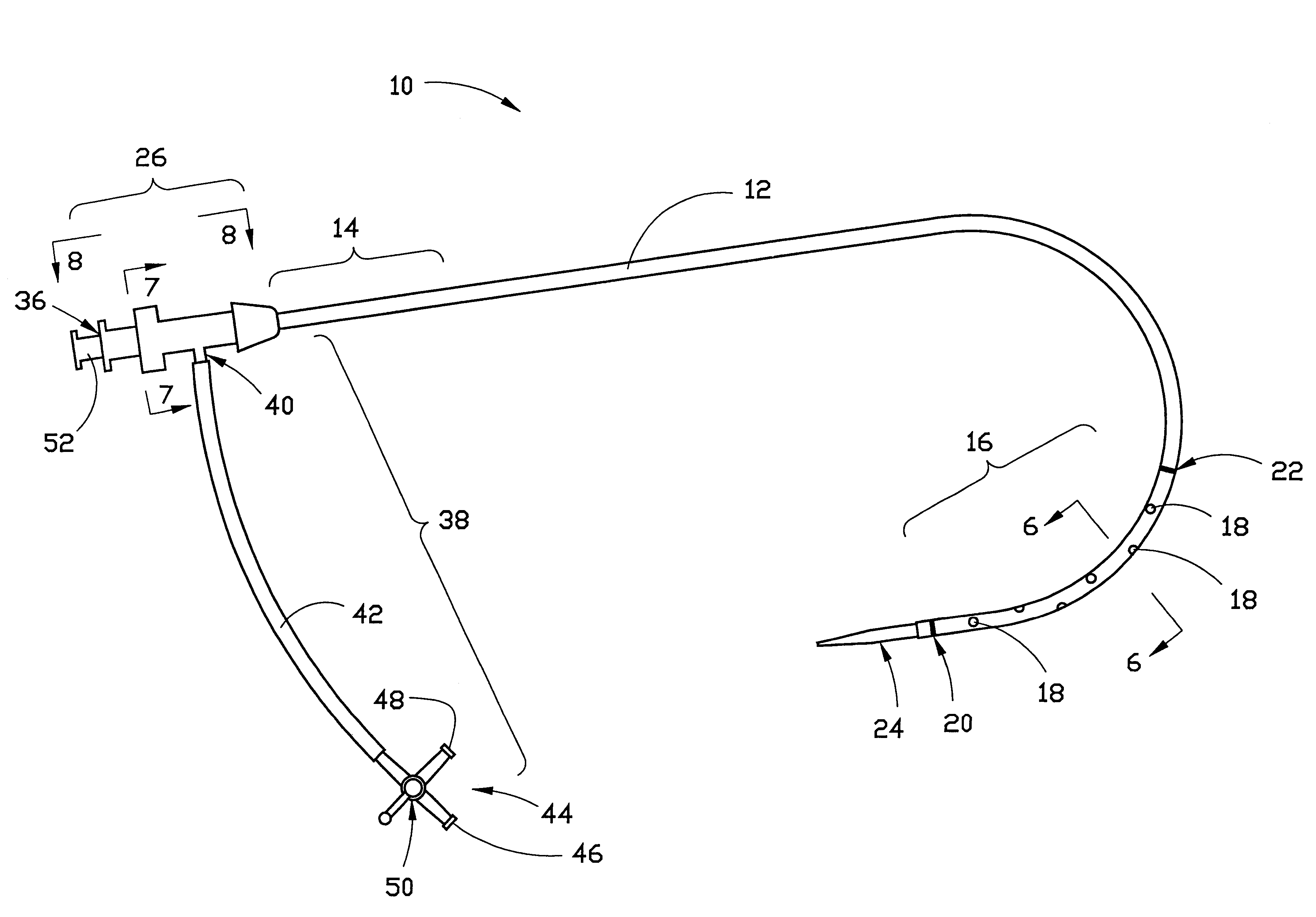
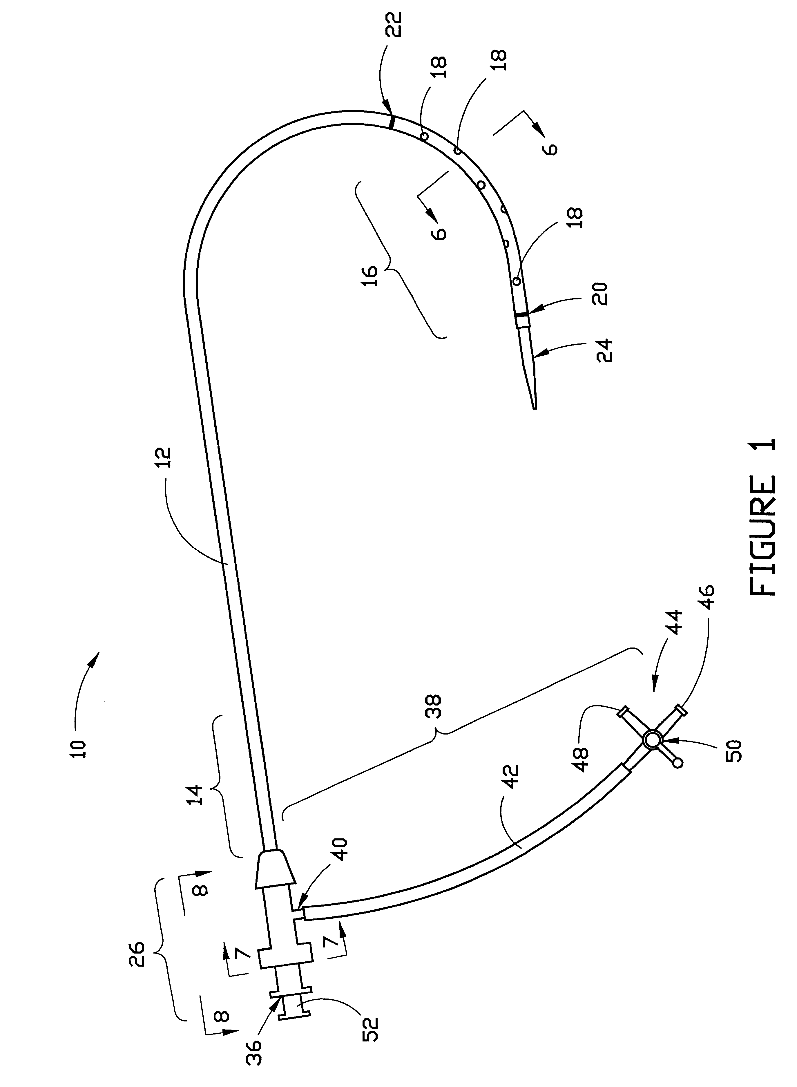
Preferably, side port 38 of hub 26 is adapted to rotate about the long axis of tube 12. This may be accomplished in several ways, three of which are illustrated in FIGS. 8, 9 and 10-11. As shown in FIG. 8, attachment member 28A and secondary hub portion 29A may be fixed together, and attachment member 28A may be adapted for rotation about tube 12 between flared portion 30 and shoulder 32. FIG. 9 illustrates the hub, in which attachment member 28B is provided with an annular lip 60 at its lower end (as shown in FIG. 9), and retaining ring 61. Secondary hub portion 29B is also provided with an annular lip 62 at its upper end (as shown in FIG. 9) that may be retained within attachment member 28B and between its lip 60 and its retaining ring 61 so that side port 38 of the hub may rotate about axis 35 that extends generally along the length of the tube. Gasket 64 may be interposed between lip 60 of attachment member 28B and lip 62 of secondary hub portion 29B in order to seal the hub ass...

third embodiment

FIGS. 10 and 11 illustrate the hub which employs a Touhy-Borst type sealing mechanism. In this embodiment, secondary hub portion 29C is connected to attachment member 28B in the same manner as in the embodiment of FIG. 9 so that side port 38 of the hub may rotate about axis 35. Secondary hub portion 29C includes inner component 66 and outer component 68. Inner component 66 is externally threaded with threads 70. Outer component 68 is internally threaded with threads 72, which are adapted to mate with threads 70. Outer component 68 also includes inner cylinder 74, which is hollow and opens at its outer end into end port 36. Inner cylinder 74 is also internally threaded with threads 54 that are adapted to mate with terminus 52 of the dilator. At the inner end of cylinder 74 is washer 76, a generally rigid, circular washer having a central hole therethrough. Cylinder 74 of outer component 68 is adapted to move axially, as the outer component is threaded onto the inner component, into r...


PUM


Abstract

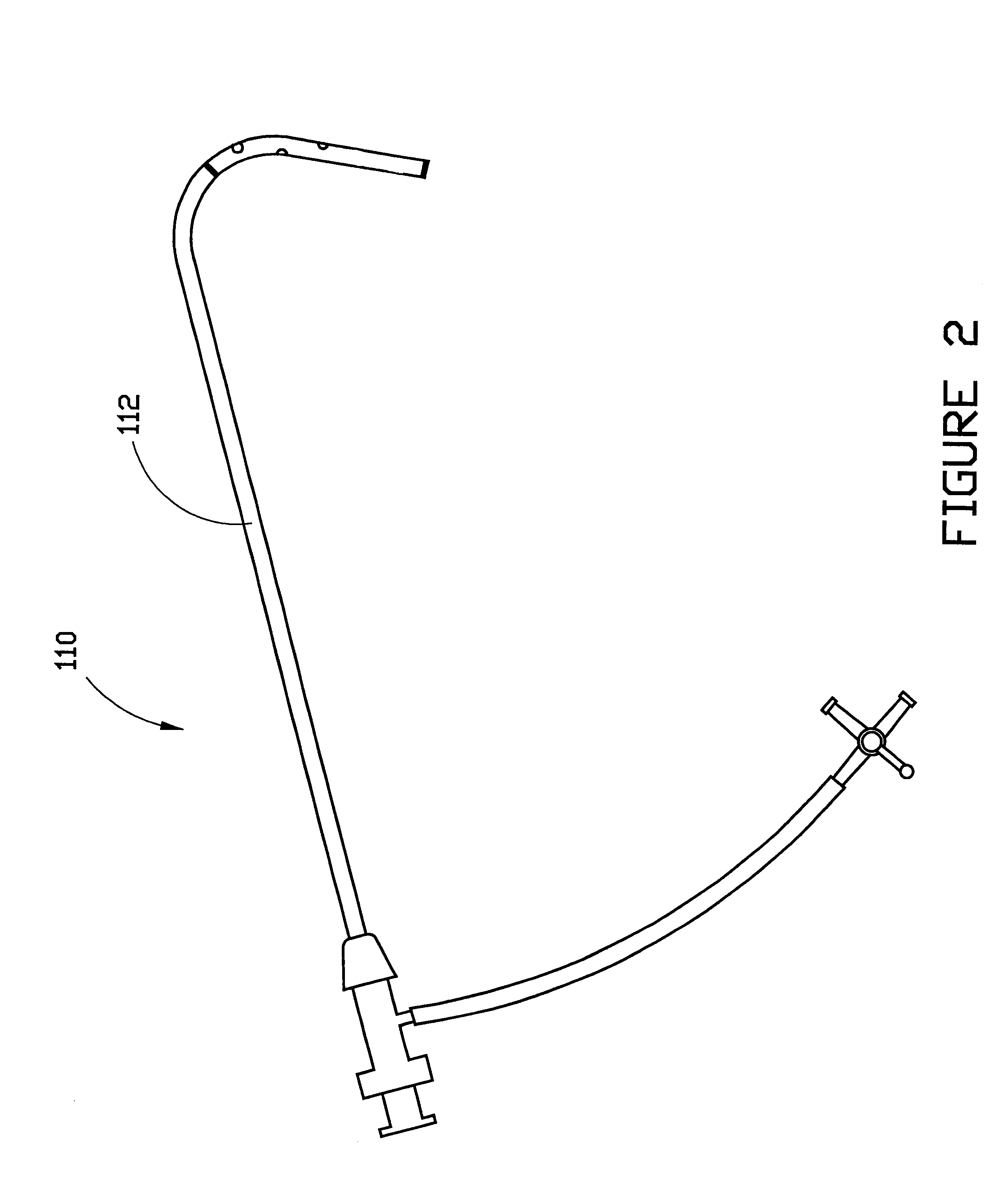
A vascular interventional device may be introduced over a guidewire into a vessel of the cardiovascular system of a patient. This device includes a hollow, flexible tube having a proximal end and a distal end that is adapted to selectively engage a target vessel of the cardiovascular system of the patient. This tube also includes a lumen that is continuous from the proximal to the distal end, and has an end hole in the distal end that is in fluid communication with the lumen. A plurality of side holes are provided near the distal end of the tube, each of which is in continuous fluid communication with the lumen. The device also includes a hollow vessel dilator that is adapted for insertion into and through the tube and over the guidewire. The dilator has an inside diameter that is slightly larger than the guidewire and an outside diameter that is slightly smaller than the diameter of the lumen of the tube. The distal end of the dilator is adapted to accommodate vascular entry over the guidewire, and the dilator is adapted to dilate the vessel to accept the tube. The device also includes a hub at the proximal end of the tube. The hub includes an end port through which a second interventional device having an outside diameter smaller than the diameter of the lumen may be introduced into the lumen of the tube. The hub also includes a side port through which a fluid agent may be injected for delivery through the lumen and out the end hole and side holes of the tube. A sealing mechanism is also provided in the hub to prevent air from entering the tube and blood and other fluids from leaking out of the tube through the hub. A pair of vascular interventional devices, at least one of which is constructed according to the invention, may be utilized to treat or study a cardiovascular condition, or to measure the blood pressure across a vascular segment.

Description

This invention relates generally to a vascular interventional device that may be introduced over a guidewire into a vessel of the cardiovascular system of a patient. More particularly, the invention relates to such a device that functions both as a vascular entry sheath and as a diagnostic or therapeutic catheter. Such a device is capable of delivering both diagnostic and / or therapeutic agents, as well as other interventional devices, to a specific target portion of the cardiovascular system of a patient.EXPLANATION OF TECHNICAL TERMSAs used herein, a vascular interventional device or interventional device is any device that may be passed through a portion of the cardiovascular system of a patient for diagnostic or therapeutic purposes, including diagnostic and therapeutic catheters. The term also includes components of such devices and other instruments that may be used to facilitate the passage of such devices within the cardiovascular system, such as guidewires, dilators and shea...

Claims


Application Information

Patent Timeline
Patent Type & Authority Patents(United States)
IPC IPC(8): A61M25/00A61M29/00
CPCA61M25/0041A61M25/0097A61M29/00A61M2025/0681
Inventor STRATIENKO, ALEXANDER ANDREW
Owner STRATIENKO ALEXANDER ANDREW
Learn More