Peeling apparatus with segmented roller assemblies

a technology of roller assembly and peeling machine, which is applied in the field of peeling machine, can solve the problems of shrimp slime and other debris splashing into the exposed gear mechanism, a time-consuming task of roller replacement, and a lot of trial and error

Inactive Publication Date: 2001-06-19
THE LAITRAM CORP
View PDF24 Cites 37 Cited by
  • Summary
  • Abstract
  • Description
  • Claims
  • Application Information

AI Technical Summary

Benefits of technology

Different versions of the releasable connection between the peeling roller and the drive member are possible. For example, a frustoconical extension from the roller into a mating receptacle forms a connection. The adjustment element, such as a bolt, extending into the roller connection structure presses the extension tightly into the mating receptacle. In another example, the connection comprises a splined, taper lock that is effective in providing both drive transmission and axial rigidity, or bending resistance, to the connection.
Besides enabling the peeling roller to be readily separated from the drive member, releasable connections can also be used to divide the peeling roller into a series of axially connected roller segments. A similar connection structure can be used between roller segments. A segmented roller has a number of advantages. Adding segments allows the lengths of the rollers to be customized for various applications. Storage of smaller roller sections rather than of complete rollers is more convenient. Segments can be made of different materials, such as rubber, polyurethane, and stainless steel, or have different surface textures to provide different peeling characteristics along the peeling channel to achieve better peeling results. A segmented roller with segments of a first diameter near the entrance of the peeler and segments of a second greater diameter near the exit end could be used to form upper and lower peeler sections as in conventional peelers. Clearly, segmented peeler rollers allow a variety of custom roller configurations to match the rollers to the product characteristics for better peeling results.

Problems solved by technology

Aligning the rollers and meshing their gears properly take a lot of trial and error, making roller replacement a time-consuming task.
Another problem is that shrimp slime and other debris can splash into the exposed gear mechanism at the top of the peeling channels.
Fouling and corrosion of the gears can result from such debris and juices.
Thus, exposure of the gears to the peeling channels is undesirable.
Because the gear is integral with the roller, other problems arise.
As one example, the gear teeth are subject to damage during handling of the heavy rollers because the teeth are exposed at the end.
Because of the gear, the rollers cannot be stored as compactly either because the gear diameter is greater than the roller diameter.
Because the extruder cannot accommodate the larger diameter of the gear, the extrusion process must be stopped for each roller.
Thus, the integral gear is not conducive a faster, continuous extrusion process.

Method used


Image

  • Peeling apparatus with segmented roller assemblies
  • Peeling apparatus with segmented roller assemblies
  • Peeling apparatus with segmented roller assemblies

Examples


Embodiment Construction

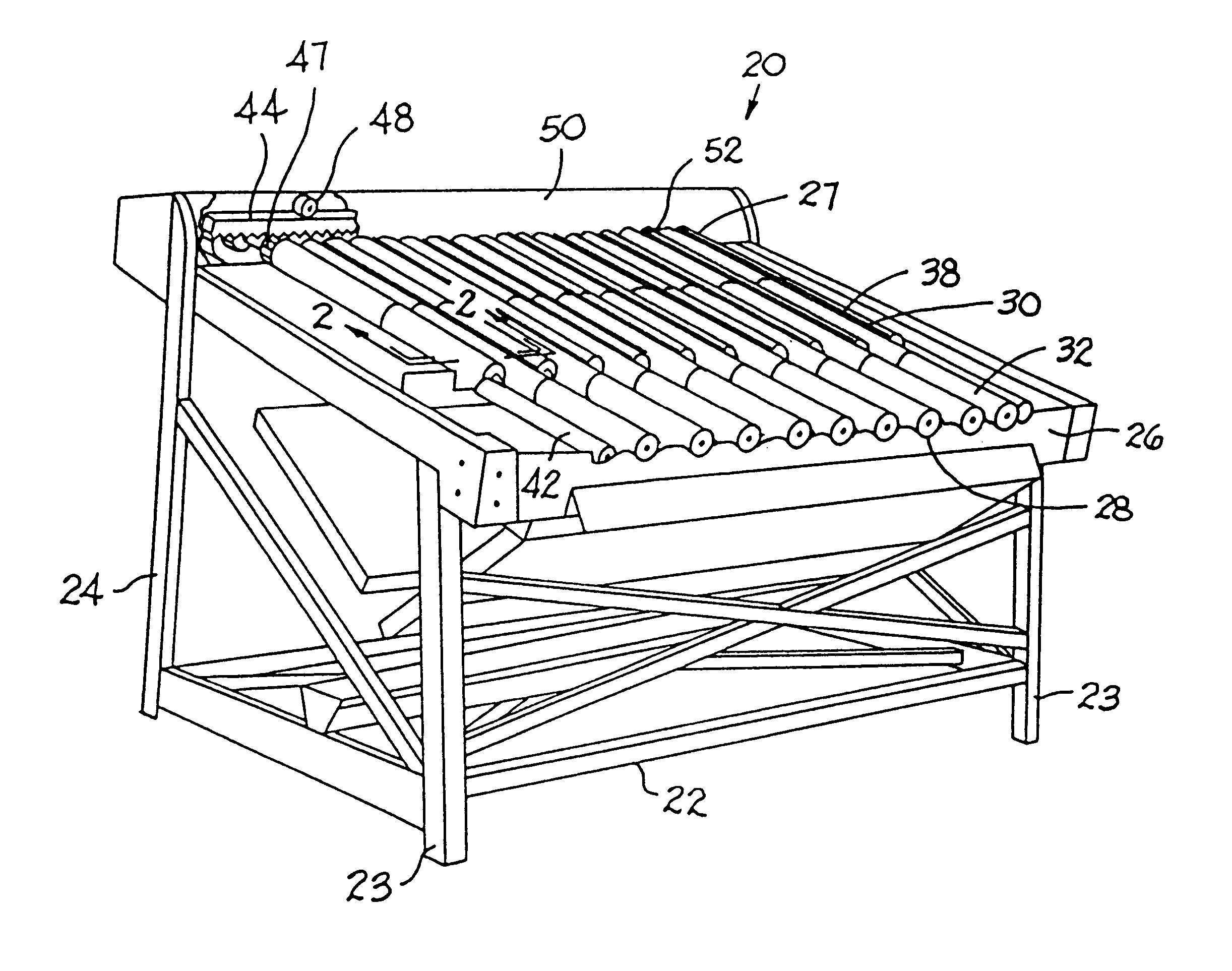
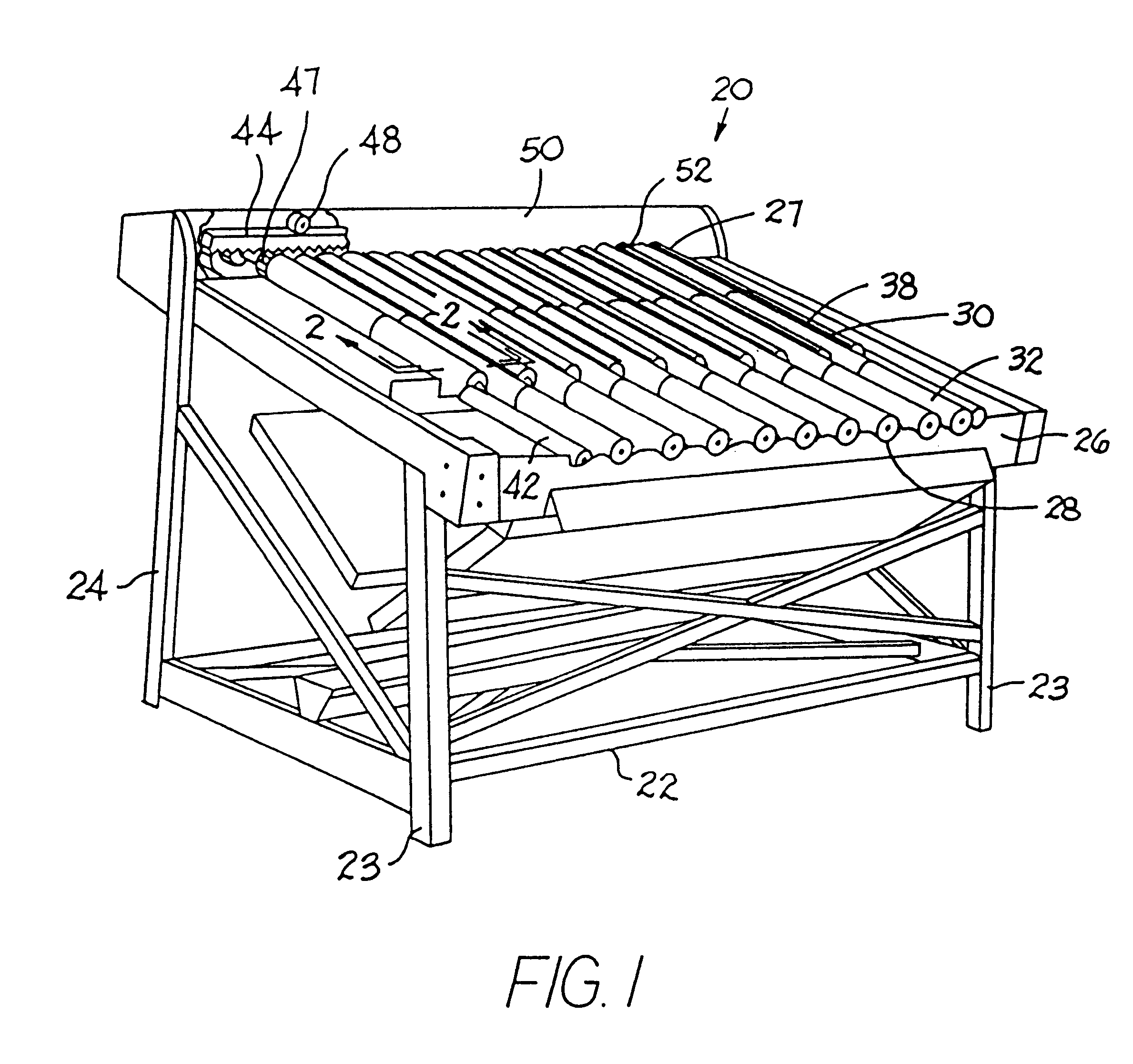
An exemplary version of a peeling apparatus embodying features of the invention is shown in FIG. 1. The peeling apparatus 20, which is typically used to peel shrimp, includes a frame 22 consisting of front and rear legs 23, 24 forming a framework with various cross-bracing and support members. A bed 26 supports peeling rollers that slope downward from a first product-entrance end 27 to a second product-exit end 28. (To simplify the drawing, a finger frame, typically used to urge shrimp into peeling positions, is not shown.) The rollers shown in FIG. 1 include two kinds of powered roller assemblies--channel-forming roller assemblies 30 and lower power roller assemblies 32. In an upper peeling portion of the peeling apparatus, a plurality of side-by-side peeling channels are formed by a roller assembly arrangement shown in FIG. 2. In the arrangement, a peeling channel is formed by a lower roller assembly 32 flanked by two channel-forming roller assemblies 30. All three roller assembli...


PUM


Abstract

Apparatus for peeling shrimp including powered roller assemblies each made up of a peeling roller and a drive member attached by a releasable connection. Roller connection structure at a first end of each roller assembly mates with reciprocal drive connection structure in the drive member. An adjustable element extending through the drive member allows the connection to be released and the roller assembly separated into a roller segment and a drive member segment. In other versions the roller segment can be composed of a series of segments having the same or different peeling surface characteristics in which the individual roller segments are similarly releasably connected.

Description

1. Field of the InventionThis invention relates to peeling apparatus and, more particularly, to roller-type shrimp-peeling machinery using an array of segmented roller assemblies to remove shells from shrimp meat.2. Description of the Related ArtOriginally introduced because of the high labor costs of peeling small shrimp by hand, shrimp peeling machines are now widely used in the shrimp processing industry. Roller-type shrimp-peeling machines, in particular, dominate the bulk shrimp peeling industry. U.S. Pat. Nos. 2,778,055, Jan. 22, 1957, and 2,537,355, Jan. 9, 1951, both to Fernand S., James M., and Emile M. Lapeyre, describe the basic structure and principles of operation of roller-type shrimp peelers.U.S. Pat. No. 2,778,055 shows a peeling machine with a rigid framework supporting the peeling elements. A transverse beam divides the machine into two peeling sections. The upper peeling section extends from a rear wall to the beam; the lower peeling section extends from the beam ...

Claims


Application Information

Patent Timeline
Patent Type & Authority Patents(United States)
IPC IPC(8): A22C29/02A22C29/00
CPCA22C29/026
Inventor SIRGO, SCOTT J.GREVE, CHRISTOPHER G.ROSOW, BENLEDET, BRENT A.
Owner THE LAITRAM CORP
Why Eureka
Try Eureka