Apparatus system and method for installing and retrieving pipe in a well

a technology for installing and retrieving pipes, applied in mechanical apparatus, sealing/packing, borehole/well accessories, etc., can solve the problems of time-consuming and hazardous work, and high cost of a well directly related to the cost of a well,

Inactive Publication Date: 2001-06-26
TORRES CARLOS A
View PDF8 Cites 43 Cited by
  • Summary
  • Abstract
  • Description
  • Claims
  • Application Information

AI Technical Summary

Problems solved by technology

The work is time consuming and can be hazardous.
The cost of a well is directly related to the time required to construct the well.
The cost considerations become critically important in the drilling of deep-water wells because the deep water drilling rigs and the required support services are extremely expensive.
Operating costs of $10,000 per hour, or more, may be incurred in deep- water drilling operations.
Deep-water drilling rigs employ specialized, complex equipment to store, assemble, and disassemble the pipe strings.
However, using conventional techniques, the derrick height places a practical limit on the length of the stands.
While coiled pipe may be quickly injected into and retrieved from a well, it has limited use in well construction.
Coiled pipe suffers from the disadvantage of not being rotatable within the well.
Moreover, the require

Method used


Image

  • Apparatus system and method for installing and retrieving pipe in a well
  • Apparatus system and method for installing and retrieving pipe in a well
  • Apparatus system and method for installing and retrieving pipe in a well

Examples


Embodiment Construction

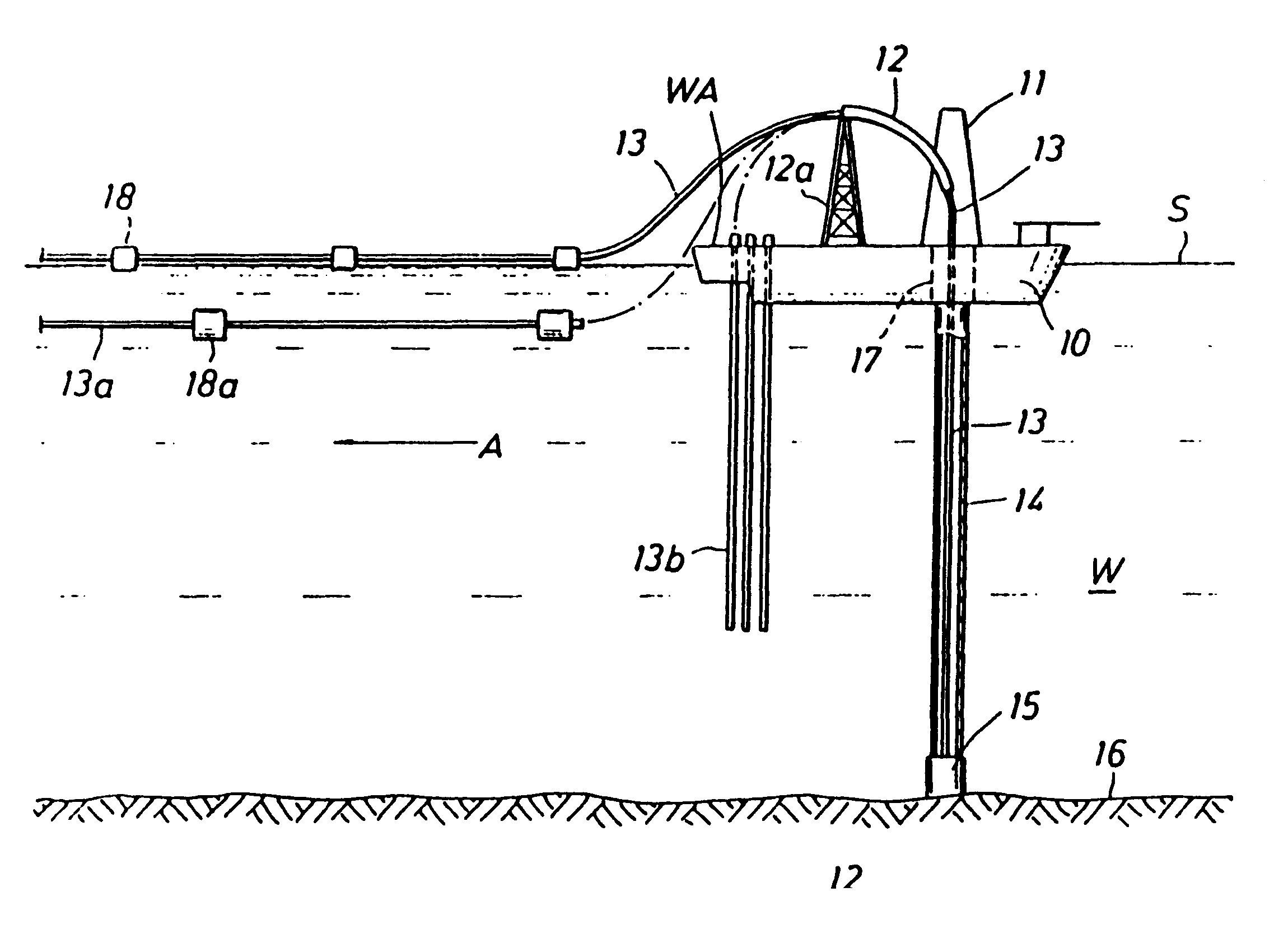
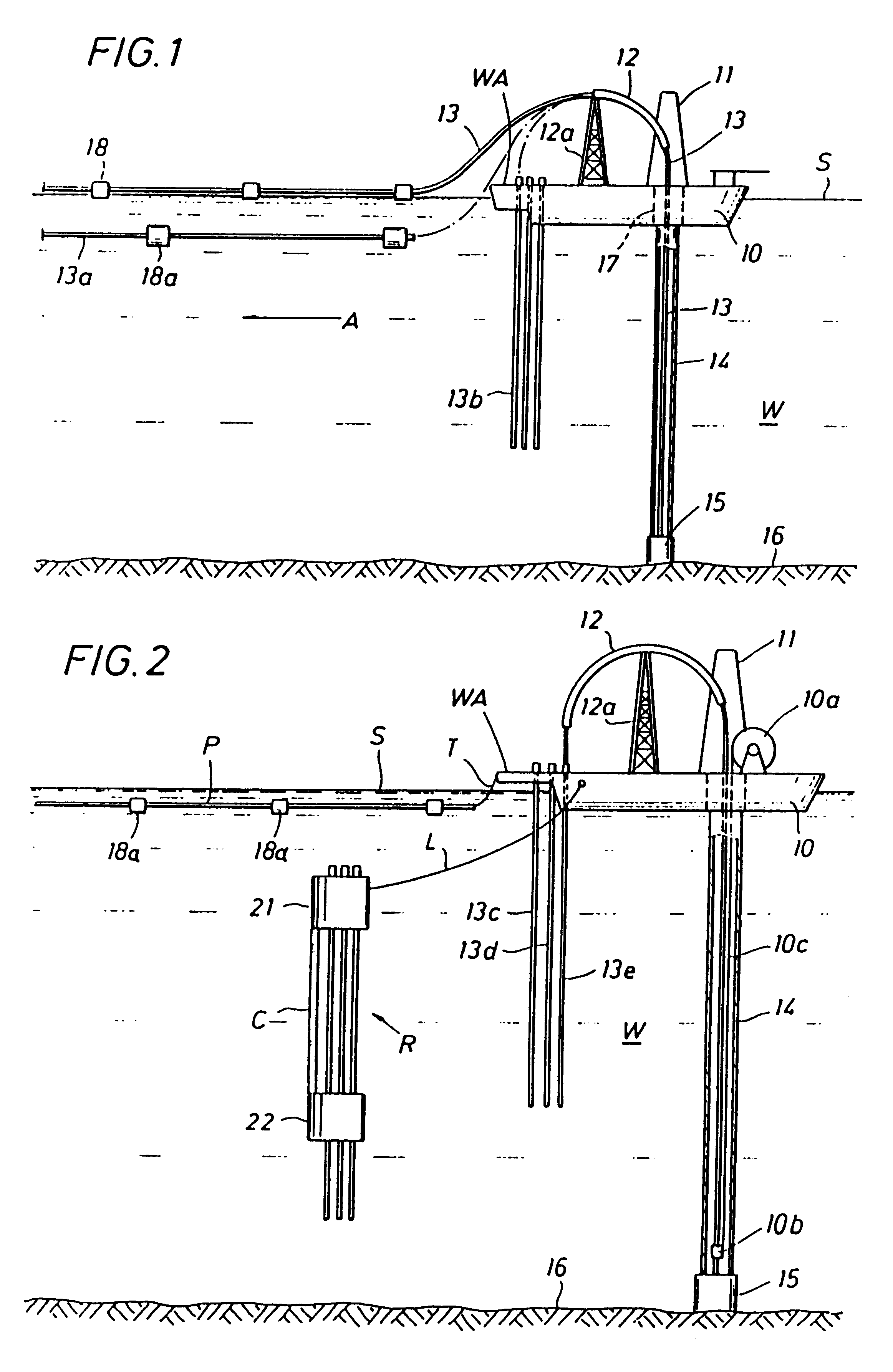
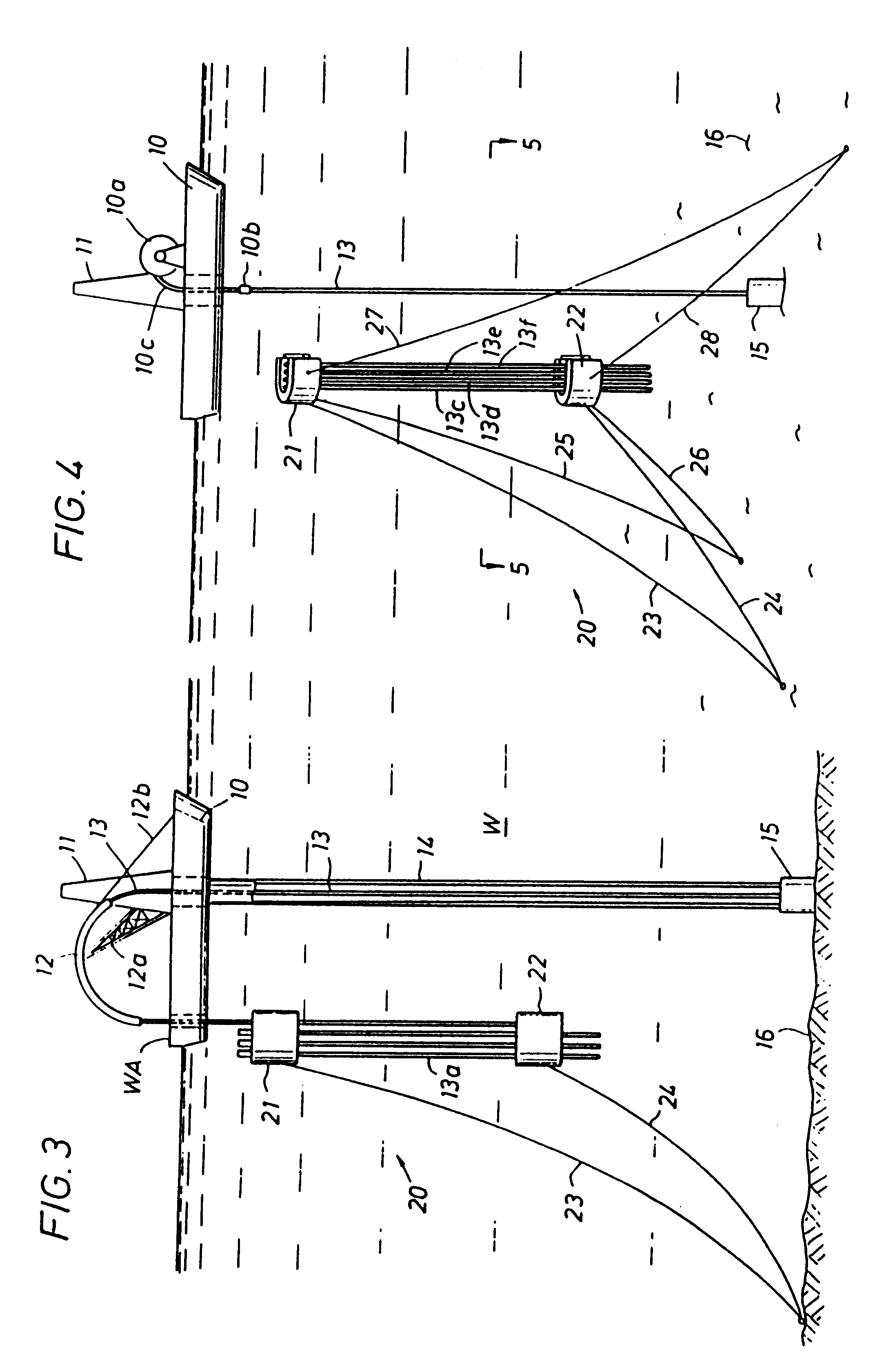
With reference to FIG. 1, a drilling rig represented by a drill ship 10 provides a drilling platform with a mast 11 and a curving guide 12. The rig is illustrated extracting a string 13 from a marine riser pipe 14. The curved guide may be a tubular body or other suitable device such as a roller-guided track as commonly used to run coil tubing. Positive driving means may be included in the curved guide to move the pipe through the guide. The guide 12 is supported by a tower 12a.

The riser pipe 14 extends from a subsurface wellhead 15 supported on the seabed, through a body of water W and into a moon pool 17 of the drilling platform 10.

When pulling the string 13 out of the riser 14, the free end of the string is directed into the open end of the guide 12 and pushed through the guide to the far end of the guide and out onto the surface S of the body of water W. The traveling block or top drive of the rig 10 may provide the force moving the pipe or the force may be provided by other know...


PUM


Abstract

Pipe used in drilling and/or completing wells is stored in long rectilinear segments or strings in the space adjacent a drilling rig being used to construct a well. The pipe is introduced into the well, or extracted from the well, in long segments made up of multiple individual pipe sections. In one embodiment, long rectilinear segments of pipe are bent into a curve that extends from the rig to the space surrounding the rig, where the pipe re-assumes its rectilinear shape. The curve radius is greater than the pipe's yielding bending radius. On a water-based rig, the pipe is received in the water surrounding the rig where it may be stored, tested, inspected, reassembled, treated, and/or otherwise processed. The pipe may be received within a long pipe storage sleeve that is buoyed laterally at or below the water surface or it may be secured to a guy line anchored between the rig and the water bottom. In deepwater applications, long sections of the pipe are stored vertically in the water area between the surface drilling rig and the water bottom. The pipe may also be stored within vertically oriented storage sleeves. In a modified form of the invention, the long pipe sections are moved laterally for storage in the area between the rig and the water bottom without being first pulled to the water surface. The bottom of each stored section is made up or broken out at the subsea wellhead. The pipe section may also be stored within the riser.

Description

BACKGROUND OF THE DISCLOSURE1. Field of the InventionThe present invention relates generally to the construction of wells and more specifically to the handling and storage of pipe used in the drilling, completion and workover of wells. The primary applicability of the invention is for wells constructed through deep-water bodies of 3,000 ft. or more in depth. The invention also has utility in the construction of certain onshore wells and offshore wells drilled through shallower water bodies.2. Background of the Prior ArtThe pipe used in constructing wells is typically assembled with individual pipe sections, referred to as "joints", that are secured together, end-to-end, to form a pipe string. The different pipe strings used in the construction of the well include drill strings, work strings, casing strings, and tubing strings, as well as others.The drill strings and work strings are employed in drilling and / or repairing the well. The drill strings and work strings may be run into an...

Claims


Application Information

Patent Timeline
IPC IPC(8): E21B17/00E21B17/20E21B19/22E21B19/14E21B19/15E21B19/00F16L1/19F16L1/12
CPCE21B17/20E21B19/002E21B19/143E21B19/15E21B19/22F16L1/19
Inventor TORRES, CARLOS A.
Owner TORRES CARLOS A
Why Eureka
Try Eureka