
Electrolytic pot for production of aluminum using the Hall-Héroult process comprising cooling means

a technology of hall-heroult and aluminum, which is applied in the direction of electrolysis components, separation processes, chemistry apparatuses and processes, etc., can solve the problems of large and cumbersome infrastructure of devices, large installation cost, and large modification of pots

Inactive Publication Date: 2001-06-26
ALUMINUM PECHINEY
View PDF10 Cites 42 Cited by
  • Summary
  • Abstract
  • Description
  • Claims
  • Application Information

AI Technical Summary

Benefits of technology

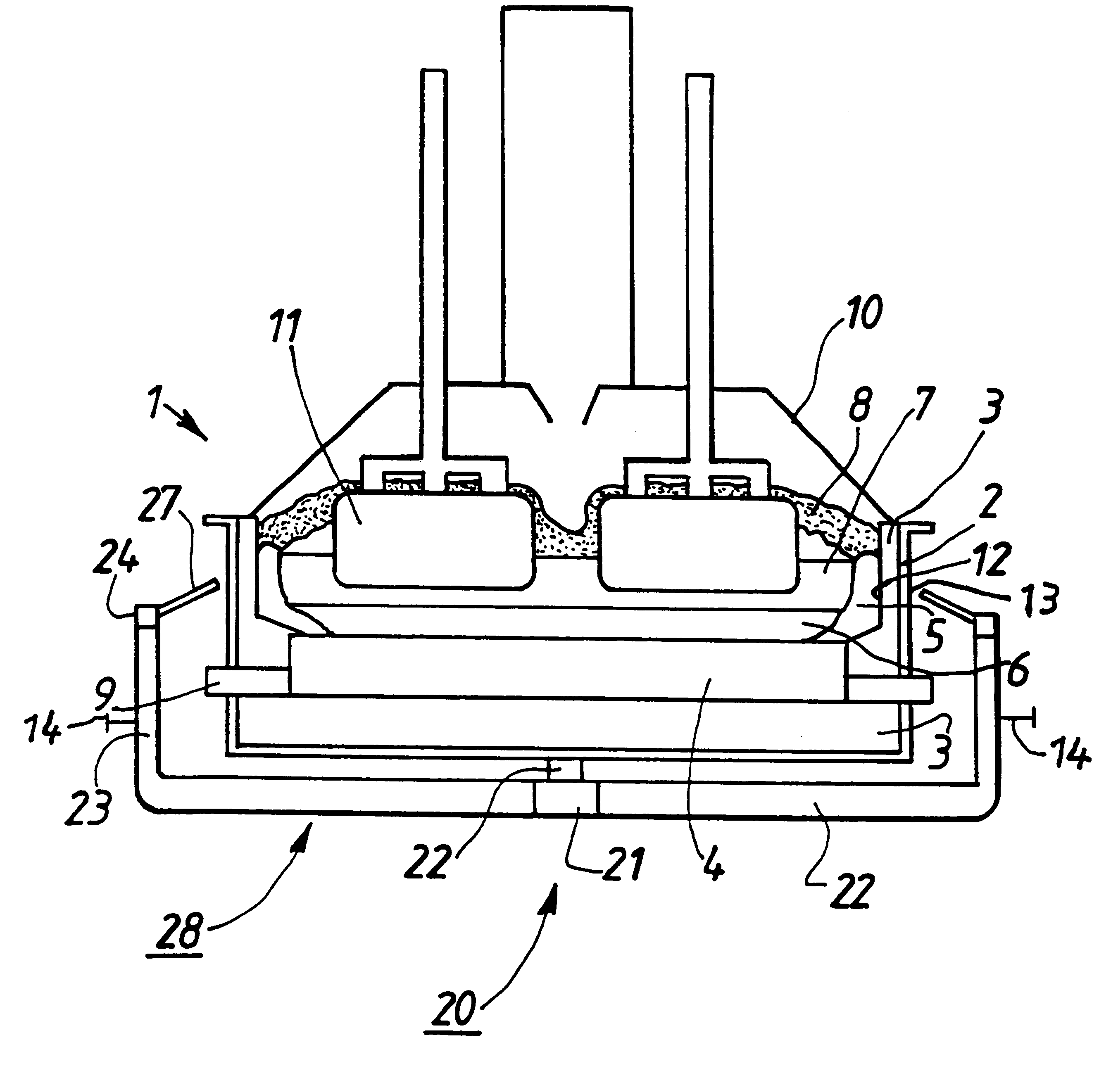
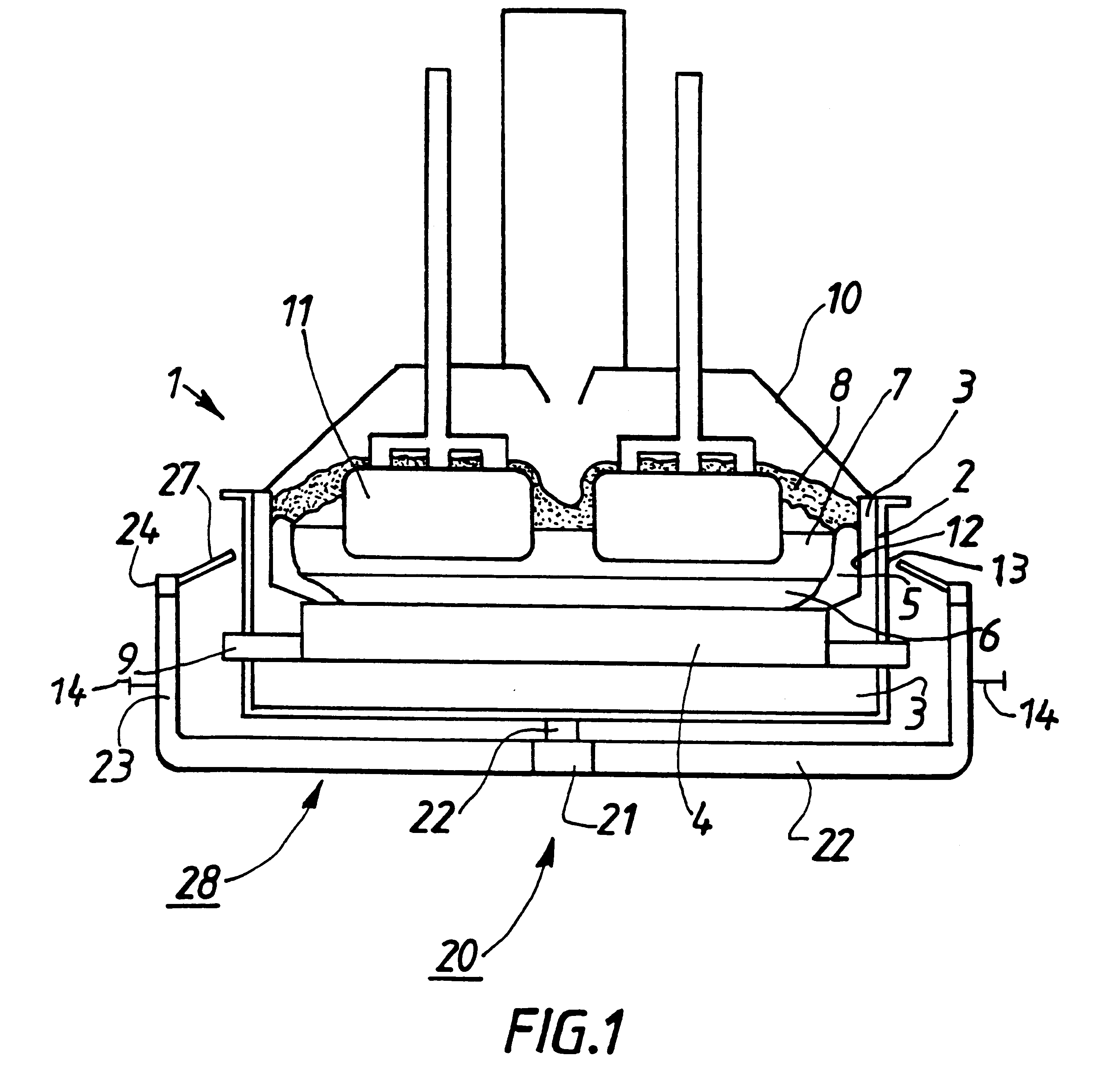
Air blown in the form of localized jets, in other words, air blown in the form of directional and confined streams, is thus blown on a relatively small area of the pot shell, in order to efficiently cool the pot wall at specific locations. The jets are distributed around the pot shell in order to fix preferred cooling areas on the surface of the pot shell. These areas are advantageously determined as a function of the heat profile of the pot, particularly in order to increase the global cooling efficiency.
The invention can thus control or modulate the power of the electrolytic pots by the addition of efficient and adaptable cooling means which may have fixed or variable extra cooling power over and above the normal power. The invention thus makes it possible to modify the power of each pot individually.
The air flow from the blower means according to the invention may be variable to enable finer control of cooling, or possibly regulation of cooling. It is also advantageous to be able to integrate means according to the invention into regulation systems used on the most modern electrolytic pots. Cooling means can then be checked or even controlled by the pot regulation system, such that the thermal flux may be regulated more efficiently, possibly in an automated manner.
The pot may include additional cooling means such as static cooling means. Cooling means may be removable, in the sense that they can be easily put into position or taken out of the pot, in some cases even while it is in operation. Thus, for example, when a pot is being tended, cooling means may be completely or partly removed. Such removal facilitates access to the pot shell and the maintenance work.
In some applications, it may be advantageous to assemble cooling means according to the invention in the form of a completely or partly automatic cooling device. This type of assembly can then be used in a global design and can very much facilitate operation. The general air flow of the device may be variable.

Problems solved by technology

These devices require a large and cumbersome infrastructure.
This solution is fairly complex, expensive to install, and also requires major modifications to the pot.
Furthermore, static devices are not very suitable for precise control of thermal fluxes.
This device requires major modifications to the pot and does not enable independent control of cooling, since regular work on the pot makes it necessary to open the collection device covers and to disturb the effect of the dampers.

Method used


Image

  • Electrolytic pot for production of aluminum using the Hall-Héroult process comprising cooling means
  • Electrolytic pot for production of aluminum using the Hall-Héroult process comprising cooling means
  • Electrolytic pot for production of aluminum using the Hall-Héroult process comprising cooling means

Examples


Embodiment Construction

Tests were carried out on 300 kA electrolytic pots with a cooling device conforming to the invention, with the following specific characteristics.

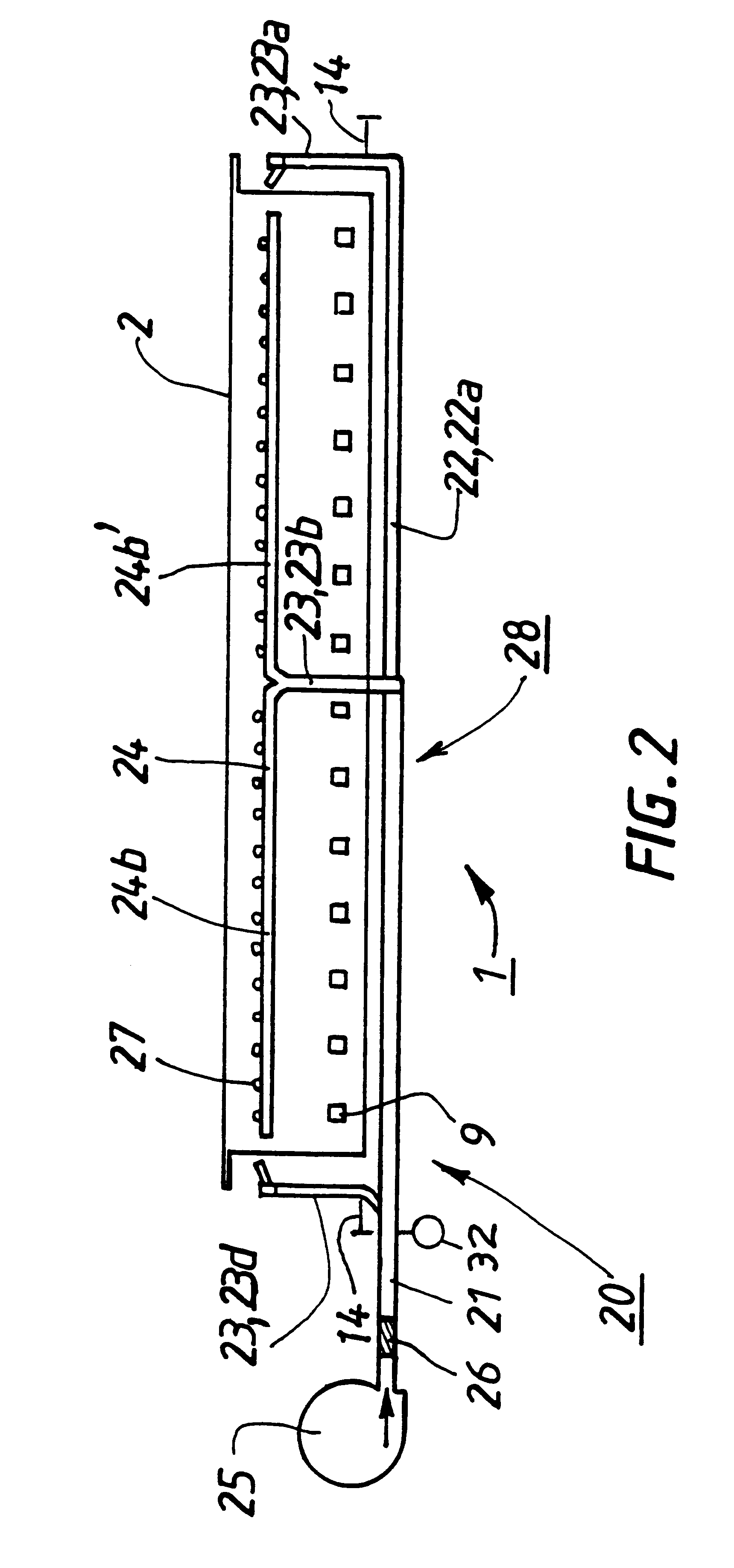
With reference to FIGS. 2 and 3, the main duct 21 passes longitudinally under the pot shell 2 until almost the center of the pot 1, and then divides into three branches 22a, 22b, 22c perpendicular to each other and with a smaller cross-section than the main duct 21. The horizontal branch 22a extends under the pot shell 2 to its other end and then forms the vertical branch 23a that rises along the head of the pot 1 approximately to the same height as the edge slab, and then splits into two horizontal branches 24a, 24a' which extend to the sides of the pot 1. The other two transverse branches 22b, 22c extend as far as the sides of the pot shell 2 and then form vertical branches 23b, 23d which rise along each side of the pot shell 2 approximately as far as the pot edge slab, and then split into horizontal branches 24b, 24b', 24c, 24c' which e...


PUM

PropertyMeasurementUnit
Speedaaaaaaaaaa
Speedaaaaaaaaaa
Speedaaaaaaaaaa

Abstract

An electrolytic pot for the production of aluminum by the Hall-Héroult electrolysis process includes a cooling device for blowing air with localized jets, advantageously with variable flow, in order to evacuate and dissipate thermal energy from the pot. An aluminum production plant using the Hall-Héroult electrolysis process has at least some pots which, either individually or in common, include at least one cooling device.

Description

1. Field of the InventionThe invention relates to the production of aluminum by igneous electrolysis using the Hall-Heroult process and installations designed for industrial use of this process. More specifically, the invention relates to control of thermal fluxes in electrolytic pots and cooling means for obtaining this control.2. Description of the Related ArtMetal aluminum is produced industrially by igneous electrolysis, namely electrolysis of alumina in solution in a molten cryolite bath called an electrolyte bath, using the well known Hall-Heroult process. The electrolyte bath is contained in a pot comprising a steel pot shell which is coated on the inside with refractory and / or insulating materials, and a cathodic assembly located at the bottom of the pot. The electrolysis current, which may reach values of more than 300 kA, generates alumina reduction reactions and also keeps the electrolyte bath at a temperature of the order of 950.degree. C. by the Joule effect.The electro...

Claims


Application Information

Patent Timeline
IPC IPC(8): C25C3/06C25C3/00C25C3/20
CPCC25C3/06C25C3/20
Inventor BOS, JEROMEFEVE, BENOITHOMSI, PIERRE
Owner ALUMINUM PECHINEY
Learn More