
Automatic high-speed pill counting apparatus

a pill counting and high-speed technology, applied in the direction of instruments, de-stacking articles, packaging goods, etc., can solve the problems of speed-up problems, errors in the counted number, and liable to become dirty pills

Inactive Publication Date: 2001-07-03
YUNITEC
View PDF5 Cites 55 Cited by
  • Summary
  • Abstract
  • Description
  • Claims
  • Application Information

AI Technical Summary

Benefits of technology

According to the invention, as has been described hereinbefore, the multistage rotational separative feeder is driven at a high speed and is driven at a low speed when a set number is approached, so that the pills can be counted fast and reliably.Since a plurality of pills are vertically accommodated in each through hole of the multistage rotational separative feeder, moreover, they are reliably allowed to fall down from the pill exit and can be reliably counted even if the multistage rotational separative feeder is driven at a high speed.Since the numerous through holes are formed in the outer circumference of the lower diametrically larger portion of the multistage rotational separative feeder, moreover, the pills are prevented from popping out to the outside of the lower diametrically larger portion and from abutting against the inner circumference of the pill hopper as the multistage rotational separative feeder rotates, so that neither the inner circumference of the pill hopper is soiled with dirt nor the pills are rubbed to become dirty.Since the lower portions of the through holes of the lower diametrically larger portion of the multistage rotational separative feeder are diverged downward, moreover, the pills can easily fall down without any bite.Moreover, the multi-row cylindrical pill hoppers are connected to the lower end of the single mass hopper, and the individual multistage rotational separative feeders in the multi-row cylindrical pill hoppers are driven at a high speed. When the set number is approached, only one multistage rotational separative feeder is driven at a low speed whereas the drive of the remaining multistage rotational separative feeders is interrupted. When the set number is reached, all the drive motors are inactivated. As a result, the pills can be counted at a higher speed and without fail.

Problems solved by technology

In this series feeder system, the conveyance path is elongated to make the pills liable to become dirty.
If the oscillations are intensified, an error is caused in the counted number by an overlap of pills.
This frequently raises problems in the speed-up.
In the aforementioned separate feeder system, however, the pills are rubbed by the inner wall of the cylindrical portion so that the inner wall becomes dirty.
Moreover, the powder agglomerates, when it is discharged, to raise a problem in the safety of medicine.
Moreover, the pill exit has such a restricted opening as to catch the pills thereby to damage or break them.
Thus, this system is not suitable for the high speed so that it can be employed exclusively at a low speed.

Method used


Image

  • Automatic high-speed pill counting apparatus
  • Automatic high-speed pill counting apparatus
  • Automatic high-speed pill counting apparatus

Examples


second embodiment

Next, a second embodiment will be described with reference to FIG. 6.

first embodiment

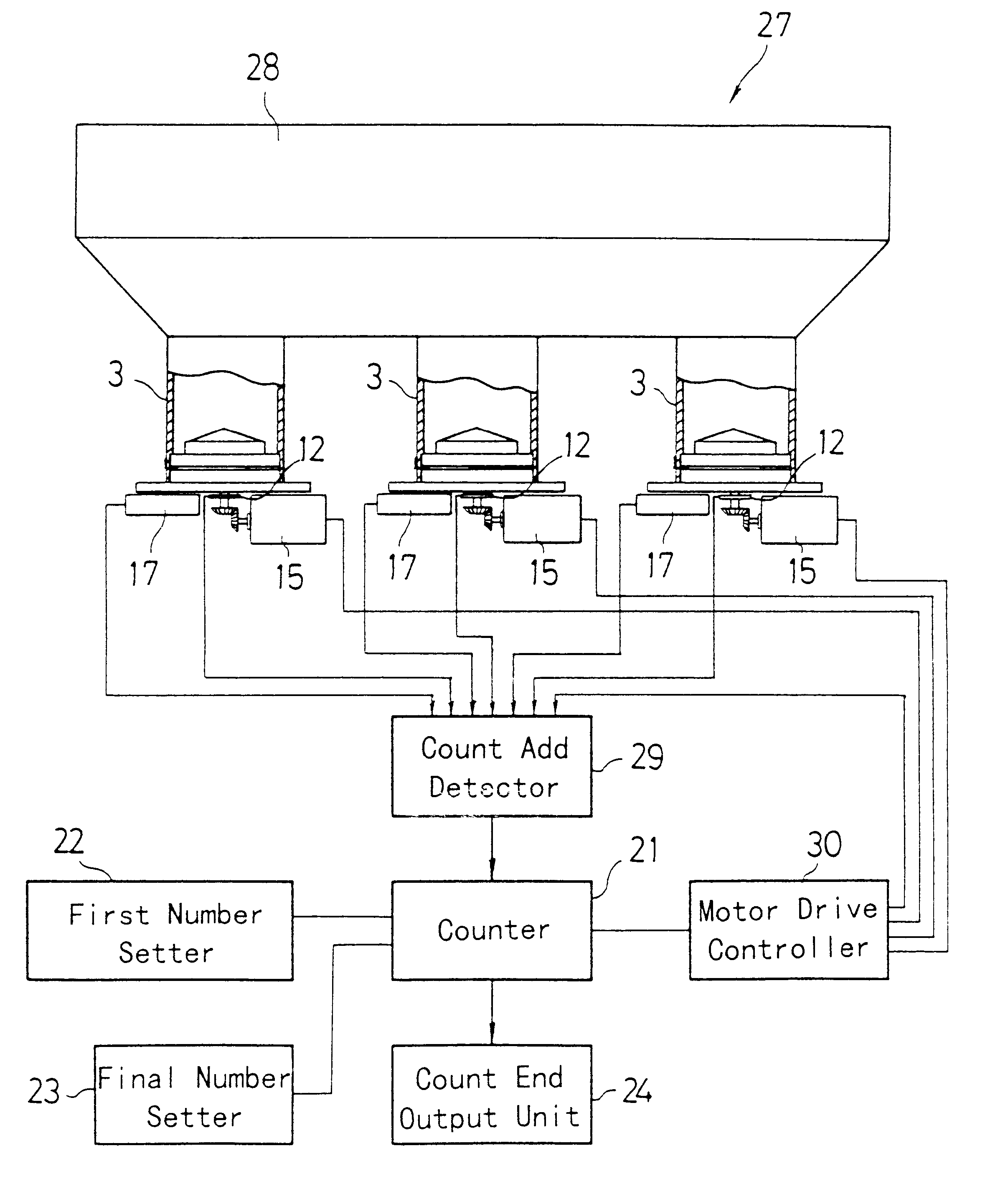
As shown in FIG. 6, a multi-row automatic high-speed pill counting apparatus 27 is constructed like the foregoing first embodiment, excepting that it is equipped with a single mass hopper 28, that the multiple rows of the aforementioned pill hoppers 3, 3 and 3 are connected to the lower end of the mass hopper 28, that the count detector 20 is replaced by a count add detector 29, and that the motor drive controller 25 for controlling the drive of the single rotational separative feeder drive motor 15 is replaced by a motor drive controller 30 for controlling the drives of a plurality of rotational separative feeder drive motors 15.

At first, the numerous pills P, are poured into the upper mouth of the mass hopper 28 so that the multiple rows of pill hoppers 3, 3 and 3 are charged with the pills P. When the individual rotational separative feeder drive motors 15 are driven under this state, the individual multistage rotational separative feeders 5 are rotated so that the pills P drop f...


PUM


Abstract

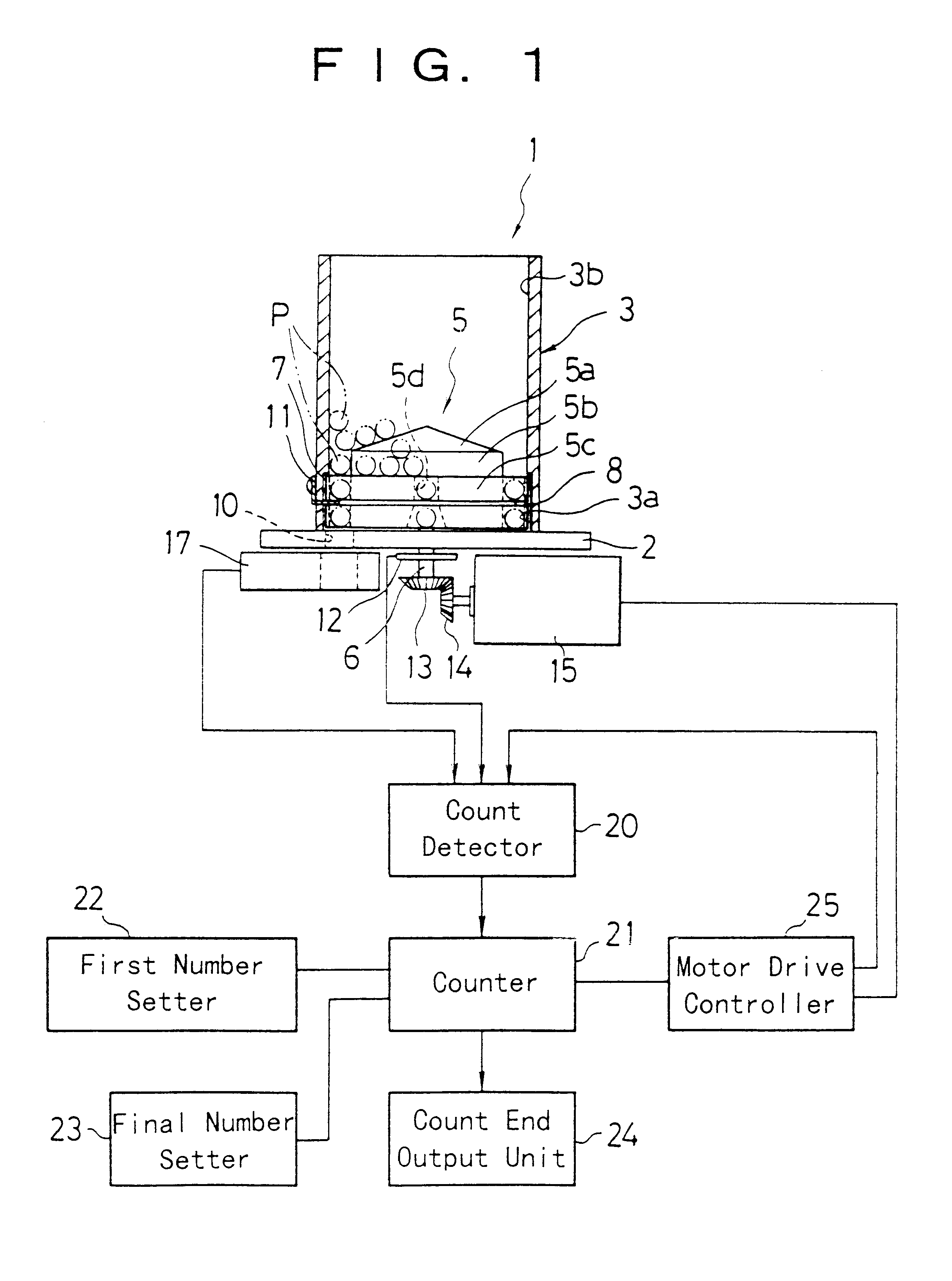
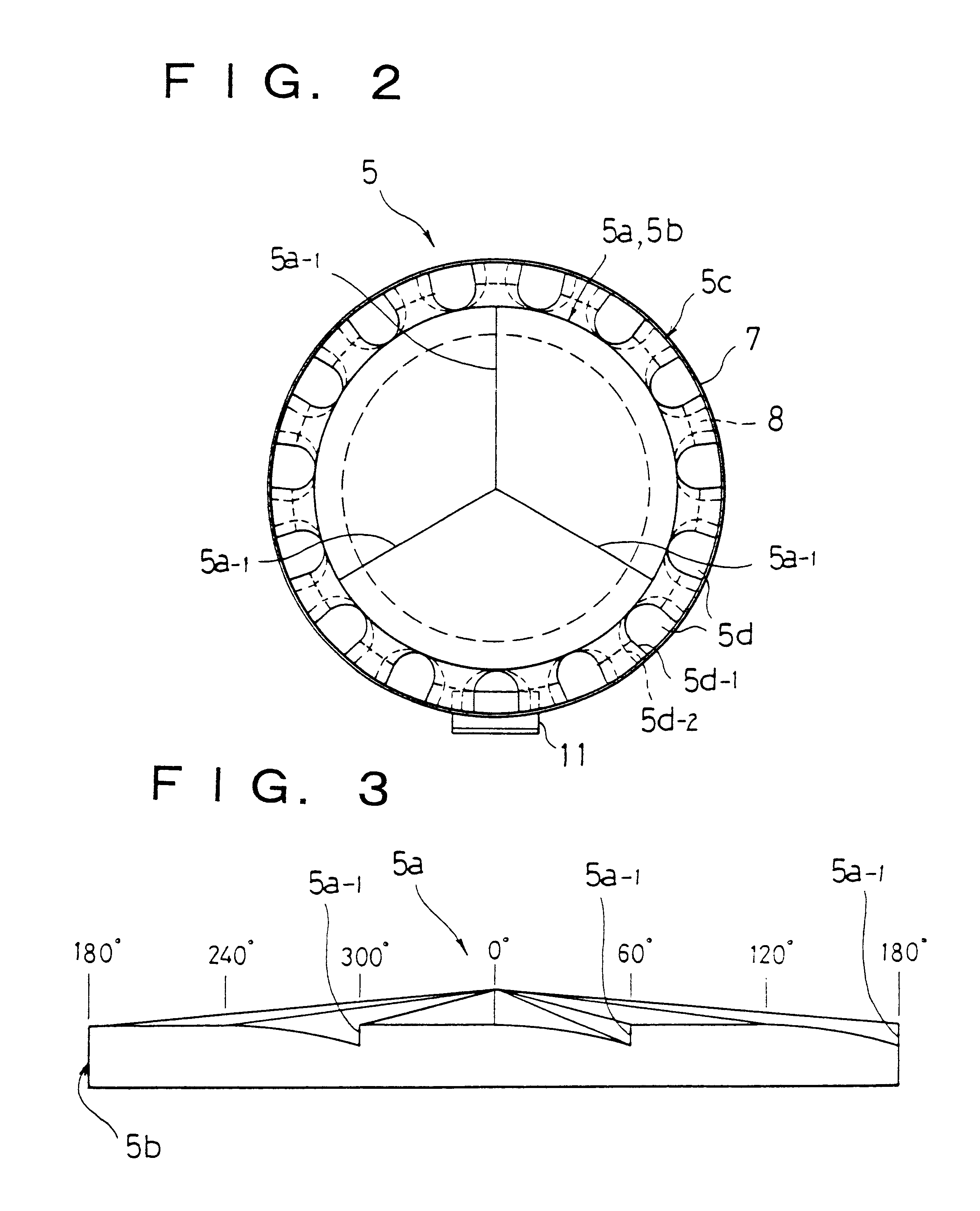
An automatic high-speed pill counting apparatus comprising: a cylindrical pill hopper 3 having a pill exit 10 and a center hole in a base plate 2; a rotational separative feeder 5 mounted in the cylindrical pill hopper and removably fitted on a shaft 6 borne in the center hole of the base plate, the feeder including an upper diametrically smaller portion 5b and a lower diametrically larger portion 5c having an external diameter approximate to the internal diameter of the lower portion of the pill hopper, a multiplicity of vertically through holes 5c being formed in the outer circumference of the lower diametrically larger portion and allowed to come into alignment with the pill exit for accommodating a plurality of pills vertically, the multiple vertically through holes 5d being enlarged at their lower portions, a ring-shaped slit 8 being formed in such a position in the outer circumference of the lower diametrically larger portion as to accommodate substantially one pill from the bottom; and a pill separating plate 11 mounted on the cylindrical pill hopper 3 above the pill exit and having an inwardly projected tip fitted loosely in the slit 8. The apparatus can count the pills quickly and accurately while preventing the inner wall of the cylindrical portion of the hopper from becoming dirty and the pills from being soiled or broken.

Description

1. Field of the InventionThe present invention relates to an automatic high-speed pill counting apparatus for general purposes to prevent the pills from being soiled or broken and to count the pills quickly and accurately.2. Prior ArtIn the case of counting the number of pills in the prior art, there is a system in which the pills are conveyed in a row, while being oscillated, by a part feeder or in which the pills are conveyed in multiple rows, while being oscillated, by a linear feeder, so that their number is counted at the conveyor end. In this series feeder system, the conveyance path is elongated to make the pills liable to become dirty. If the oscillations are intensified, an error is caused in the counted number by an overlap of pills. At a transfer from high- to low-speed conveyances, the oscillations have to be delicately adjusted for preventing the over-count. This frequently raises problems in the speed-up.In order to enhance the reliability in the discharge of pills the...

Claims


Application Information

Patent Timeline
IPC IPC(8): A61J7/00A61J7/02G06M11/00A61J3/06B65B1/30
CPCG06M11/00A61J7/02G07F17/0092B65B57/20B65B35/08G07F11/24G07F11/62
Inventor ISHIZUKA, AKIRA
Owner YUNITEC
Learn More