Method of producing cylindrical vibration-proofing rubber device

a technology of vibration isolating rubber and cylindrical shape, which is applied in the direction of shock absorbers, manufacturing tools, machine supports, etc., can solve the problems of causing such a harmful damage as detaching rubber, and achieve the effects of convenient manufacturing, convenient manufacturing, and convenient welding

Inactive Publication Date: 2001-07-03
YAMASHITA RUBBER CO LTD
View PDF4 Cites 8 Cited by
  • Summary
  • Abstract
  • Description
  • Claims
  • Application Information

AI Technical Summary

Benefits of technology

The axial end portion of the outer cylinder projects toward the position to give no thermal damage to the vibration insulating rubber. Hence, when the axial end portion and the bracket are joined and the joint portion of both members is laser-welded, the bracket is welded to the outer cylinder and the welding heat in this time gives no influence to the vibration isolating rubber.
Therefore, it becomes possible to weld the bracket to the outer cylinder after forming of the vibration isolating function member and to utilize a simple and small die for forming. Which make it much easy to manufacture the vibration isolating device. Moreover, since a common vibration insulating function member can be combined with various kinds of a bracket, the vibration isolating device can be manufactured advantageously.
Furthermore, since laser- welding makes it possible to weld in an extremely narrow width and a range to give thermal damage to the vibration isolating rubber becomes exceedingly narrow, the welding portion can be correspondingly approached to the vibration isolating rubber. Accordingly, the vibration isolating device as a whole can be made in a small-size and a light-weight.
The axial end portion of the outer cylinder may extend axially outwardly to the place to give no thermal damage to the vibration isolating rubber and the joint portion of an end face of the extending portion may be welded to the bracket, thereby it becomes possible to miniaturize the vibration isolating rubber device so as not to be expanded toward the radial direction. Moreover, by way of adopting the laser welding, it is possible to weld easily and with sufficient strength even in the narrow area such as the end face at the axial end portion of the outer cylinder.
The flange may be formed so as to bend radially outwardly at the end portion of the outer cylinder and to position a tip end face of the flange in a position to give no thermal damage to the rubber, and the joint portion of the end face of the flange may be welded to the bracket. Accordingly, it becomes easy to position the end portion of the outer cylinder at the place to give no thermal influence to the vibration insulating rubber, and in addition, it is possible to miniaturize the vibration isolating device so as not to expand a size thereof in an axial direction.
The step may comprise, setting melting depth by welding so as to be more than the thickness of a welded material; determining a laser output power and adequate welding speed according to the melting depth by an experiment; deciding a surface temperature limit determined through an experiment according to composition of the vibration isolating rubber; deciding an adequate distance from a welding line to a point to become less than the surface temperature limit when being welded with the selected laser output power and adequate welding speed by an experiment; and determining a position to keep the adequate distance from the vibration isolating rubber as said position to give no thermal damage to the rubber.

Problems solved by technology

By thermal damage to the vibration isolating rubber, we mean such a harmful damage as detaching the rubber from the outer cylinder or denaturalization of the rubber such as lowering the required physical property on account of the vibration isolating rubber suffering from heat more than the upper temperature limit.

Method used


Image

  • Method of producing cylindrical vibration-proofing rubber device
  • Method of producing cylindrical vibration-proofing rubber device
  • Method of producing cylindrical vibration-proofing rubber device

Examples


first embodiment

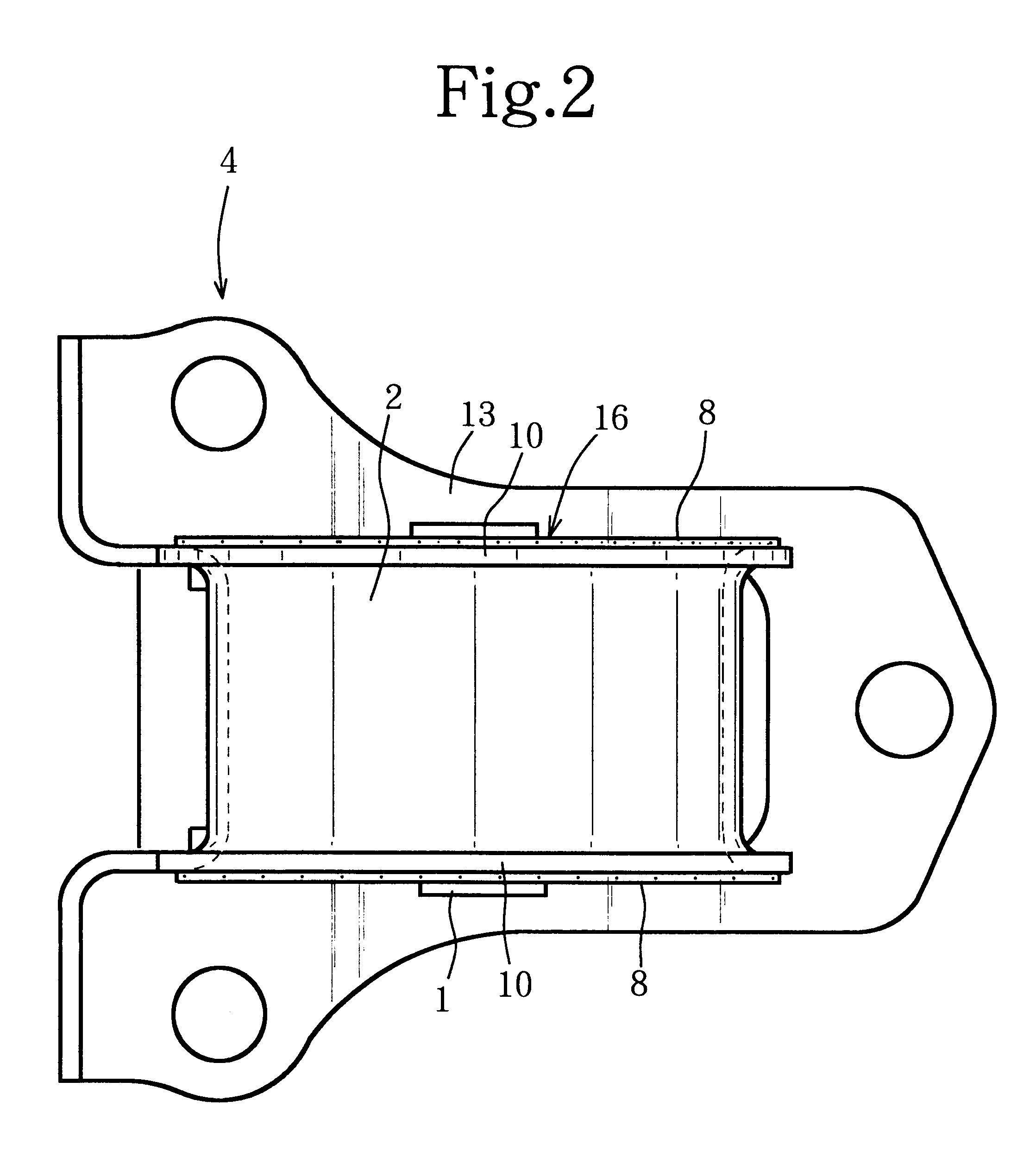
FIGS. 1 through 5 are relating to the first embodiment adapting the present invention for a cylindrical engine mount.

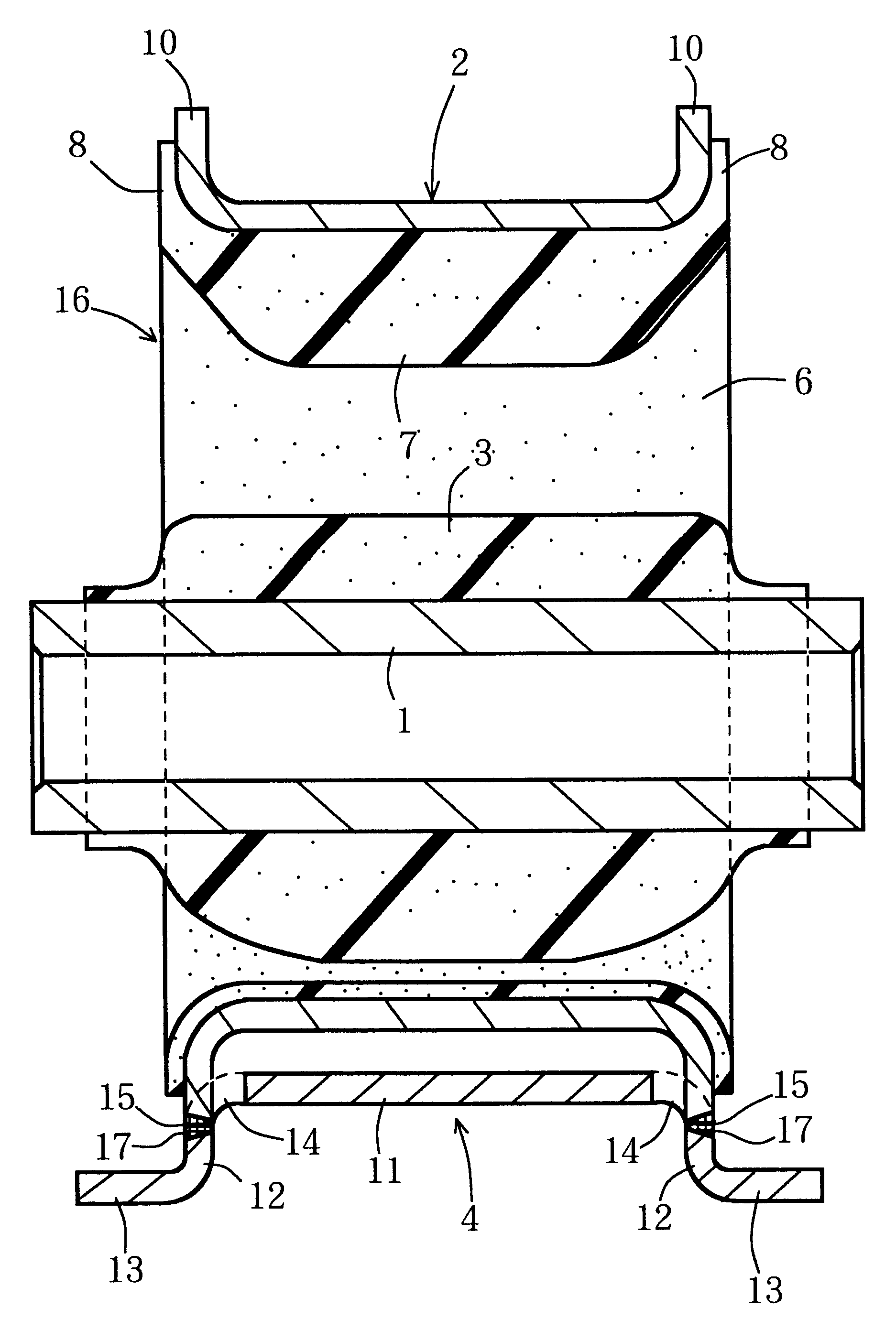
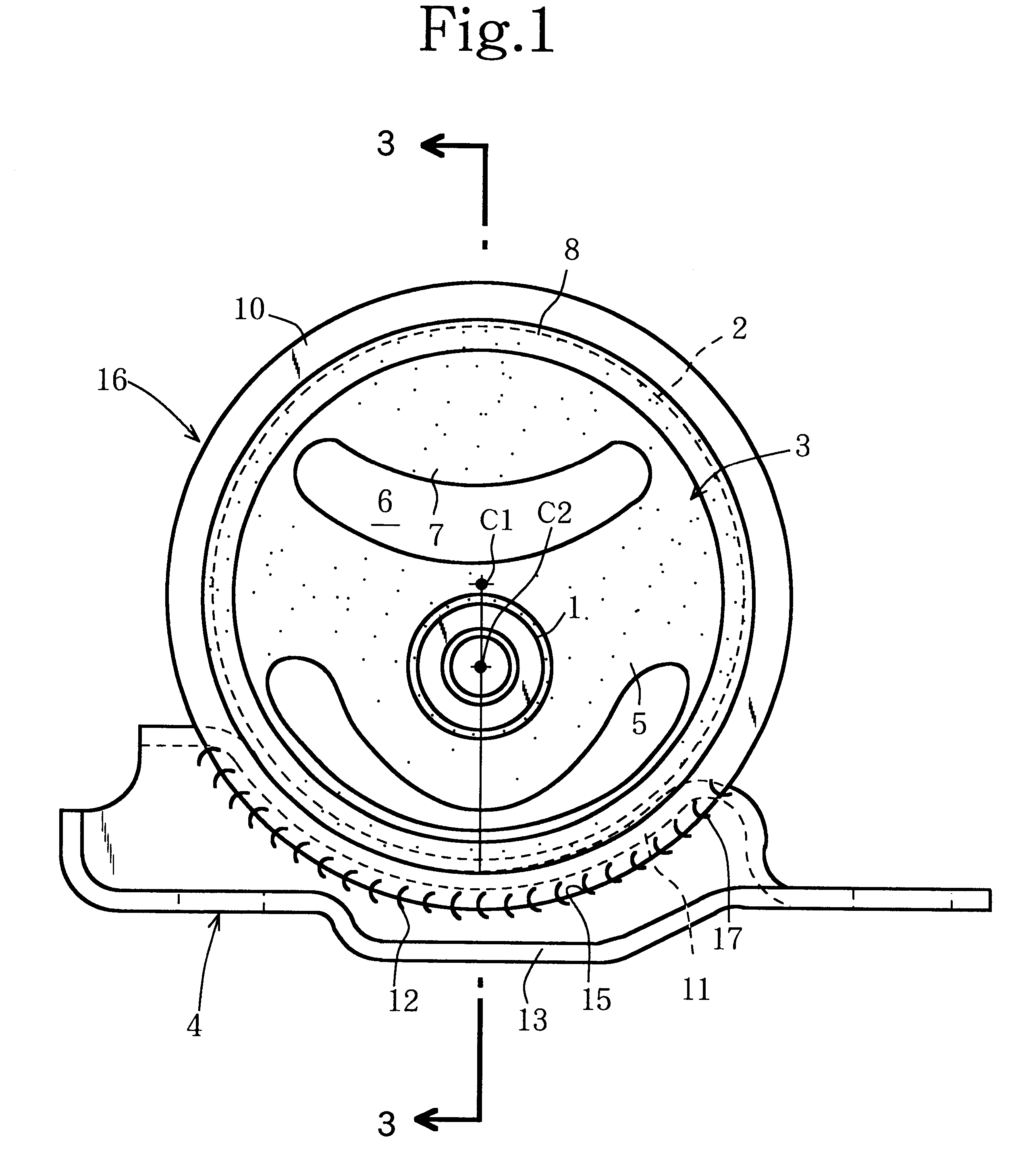
In these Figures, a vibration isolating rubber device comprises an inner cylinder 1, an outer cylinder 2, a vibration isolating rubber 3 and a bracket 4, wherein the inner cylinder 1 is arranged eccentrically inside the outer cylinder 2, and the inner cylinder 1 and the outer cylinder 2 are connected by the vibration insulating rubber 3 having a substantially V-shaped arm portion 5 as shown in the front elevational view of FIG. 1.

Reference numeral 6 denotes an axially piercing space, 7 a stopper portion projecting from a remotest part of the outer cylinder away from the inner cylinder 1 toward the inner cylinder 1, and 8 a side stopper formed along the inside of the outer cylinder 2 and projecting axially longer than the outer cylinder 2.

A flange 10 is formed so as to bend radially outwardly on the axially opposite ends of the outer cylinder 2 and the side stopper 8 i...

second embodiment

FIGS. 6 through 9 show modified examples of such device made as a cylinder-type engine mount. Hereafter, the same functional parts are explained using the same reference numerals. First, the second embodiment in FIG. 6 shows a device in which an outer cylinder 2 thereof is composed of a wound pipe. In the drawing, (A) shows a front elevation of a vibration isolating functional member 16, (B) a front elevation of a bracket 4, (C) a cross-sectional view taken on line 6--6 of (B), and (D) a cross-sectional view of a connecting portion. In FIGS. 7 and 8 also, the similar drawings are shown in (A) to (D).

As is shown in (C) of FIG. 6, the cylinder 2 is laser-welded similarly as a former embodiment in a state that a confronting portion 20 having a slit is made to be in a welding region to the bracket 4. In the case, since width of the slit becomes a tightening margin when the confronting portion is welded with the bracket side connecting surface 15, namely the outer peripheral portion of t...

third embodiment

In FIG. 7, a bracket 4 is formed in a wound pipe-like shape provided with a cylindrical fitting portion 21 and the vibration insulating functional member 16 is inserted into the fitting portion 21. The axial end portion of the outer cylinder 2 is arranged to be an extending portion 22 which extends outwardly from a vibration isolating rubber 3 by more than 7.5 mm. Each peripheral end face of the extending portion 22 and the fitting portion 21 are evenly overlapped and an overlapped portion of both members is welded on the end face thereof. In FIG. 7, (C) shows a sectional view taken on line 7--7 in (B) of FIG. 7.

When using such a procedure, since the fitting portion 21 of the bracket 4 can be formed as a wound pipe-like shape, sticking ability of the bracket 4 with the vibration isolating functional member 16 can be improved by adjusting an opening degree of a confronting portion 23. Moreover, because the flange is not provided in this embodiment unlike the former one, it is possibl...


PUM

PropertyMeasurementUnit
thicknessaaaaaaaaaa
thicknessaaaaaaaaaa
speedaaaaaaaaaa

Abstract

A vibration isolating functional member 16 is formed of an inner cylinder 1, an outer cylinder 2, and a vibration isolating rubber 3. Thereafter an end face of a flange 10 of the outer cylinder 2 is joined with a bracket side connecting surface 15 of a bracket 4 and the joint portion thereof is laser welded. In this time, the outer peripheral end face of the flange 10 as the joining portion projects toward a position apart from the vibration isolating rubber 3 such as giving no thermal influence to the vibration isolating rubber 3. This position to give no thermal influence to the rubber is determined by an experiment based on a welded material, thickness thereof, laser welding conditions (such as melting depth, output power and welding speed), surface temperature limit of the rubber and so on.

Description

The present invention relates to a manufacturing process of a cylindrical vibration isolating rubber device used for an engine mount of a vehicle and the like.1. Description of the Prior ArtVarious types of such a cylindrical vibration isolating rubber device are known. For example, such a device discloses an inner cylinder secured to one side of an engine or a vehicle body, an outer cylinder secured to another side thereof through a bracket, and a vibration isolating rubber connecting the inner cylinder and the outer cylinder, wherein the vibration isolating device is formed by means of molding including the steps of: laying the inner cylinder and the outer cylinder within a molding die such that the inner cylinder is arranged concentrically or eccentrically inside the outer cylinder, pouring liquid rubber into the die, tightening the die, and vulcanizing the rubber.In a case that a bracket is welded to an outer cylinder, if vibration isolating rubber has been beforehand baked on a...

Claims


Application Information

Patent Timeline
Patent Type & Authority Patents(United States)
IPC IPC(8): F16F1/387F16F1/38
CPCF16F1/387F16F1/3842
Inventor OZAWA, SHOGO
Owner YAMASHITA RUBBER CO LTD
Why Eureka
Try Eureka