Reduced vibration cooling device having pneumatically-driven GM type displacer

a technology of gm displacer and reducing vibration, which is applied in the direction of refrigeration machines, hot gas positive displacement engine plants, gas cycle refrigeration machines, etc., can solve the problems of noise and vibration producing problems, parts producing mechanical vibrations, and shortening the time between necessary maintenance or repairs

Inactive Publication Date: 2001-07-10
GENERAL ELECTRIC CO
View PDF17 Cites 79 Cited by
  • Summary
  • Abstract
  • Description
  • Claims
  • Application Information

AI Technical Summary

Benefits of technology

In the present invention, an elastomer "O" ring, or other elastomer shape is used at the warm end to absorb the impact energy when the displacer reaches the bottom (cold end) of the stroke, before it hits the cylinder end cap. Also, when the displacer reaches the top of its stroke, before the displacer hits the internal mechanisms of the expander, another elastomer "O" ring absorbs the kinetic energy of the displacer. It has been reported that the resultant reduction in vibration by using two resilient "O"rings, reduces the electrical noise imparted to an MRI signal by more than fifty percent.
Accordingly, it is an object of the present invention to provide an improved expander / displacer unit that is a low producer of mechanical vibration and noise.
Yet another object of the invention is to provide an improved expander / displacer that is pneumatically driven and thereby has extended operating life and simplified construction.
Yet another object of the invention is to provide an improved expander / displacer that provides a refrigeration cycle of relatively high efficiency.

Problems solved by technology

These mechanical parts produce mechanical vibrations that in many instances are undesirable and shorten the time between necessary maintenance or repairs.
However, other mechanical problems, noise and vibration producing problems arise through the use of the pneumatically-driven displacer.
These problems have roots also in the thermodynamics of the refrigeration cycle.
Thus, unless careful control is provided for the motion of the displacer, collisions can occur between the displacer piston and the closed end of the cylinder.
These collisions create noise and vibration.
Also, when the displacer moves in the opposite direction, unless careful control is provided, there can be an impact when the displacer is at the "top" of its stroke.
Further noise and vibration are produced.
However, these devices are only effective at the warm end of the displacer motion, but are not able to operate effectively at the cryogenic temperatures.
However, there is still a considerable impact and vibration problem when using delrin absorbers.
Such impacts and vibrations have been known to affect the quality and resolution of images obtained in MRI apparatuses that use cryogenically cooled magnets.
Unfortunately, elastomer materials become every rigid at the cold end temperatures so that machined bumpers of delrin continue to be used at the cold end.

Method used


Image

  • Reduced vibration cooling device having pneumatically-driven GM type displacer
  • Reduced vibration cooling device having pneumatically-driven GM type displacer
  • Reduced vibration cooling device having pneumatically-driven GM type displacer

Examples


Embodiment Construction

:

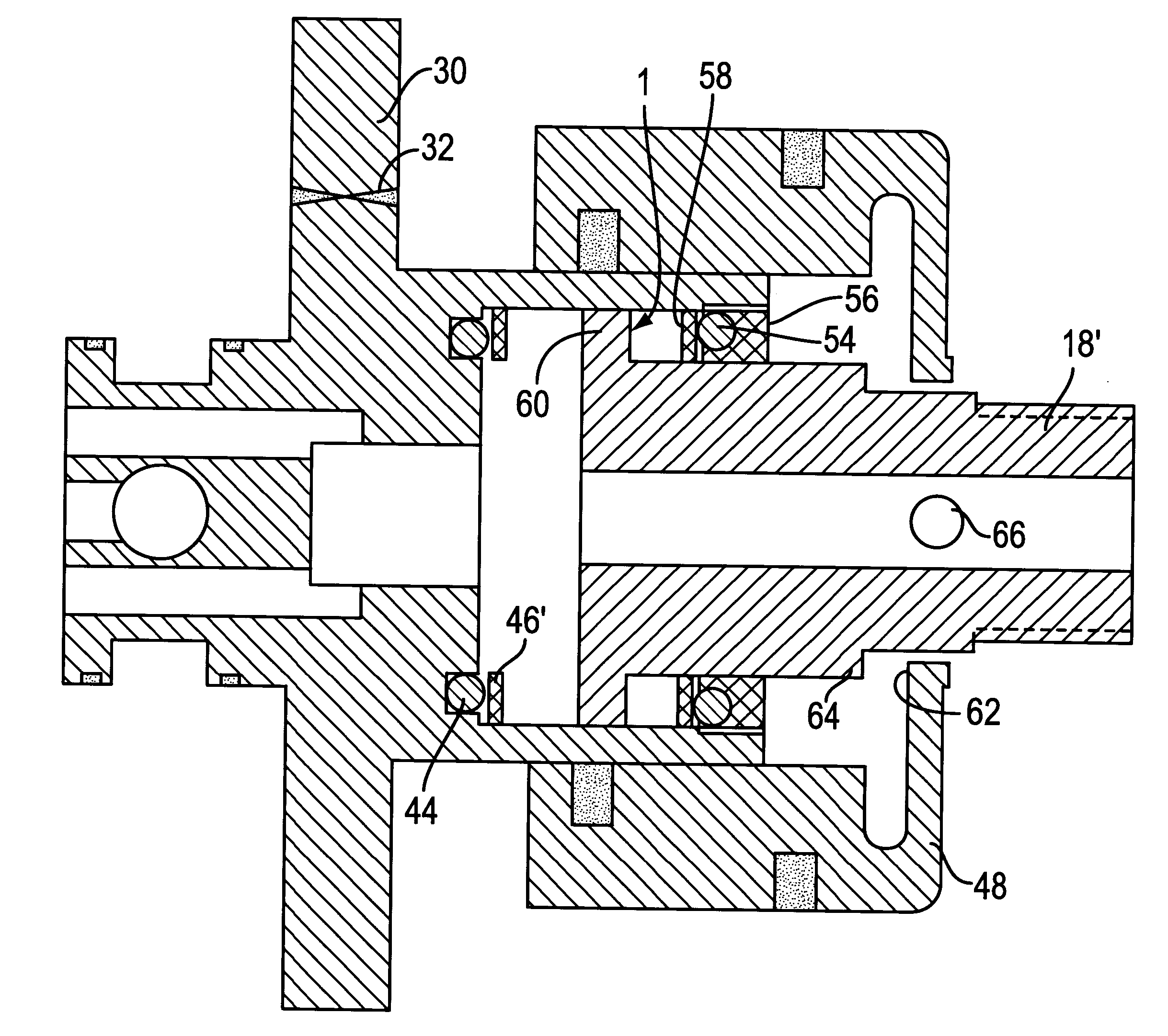
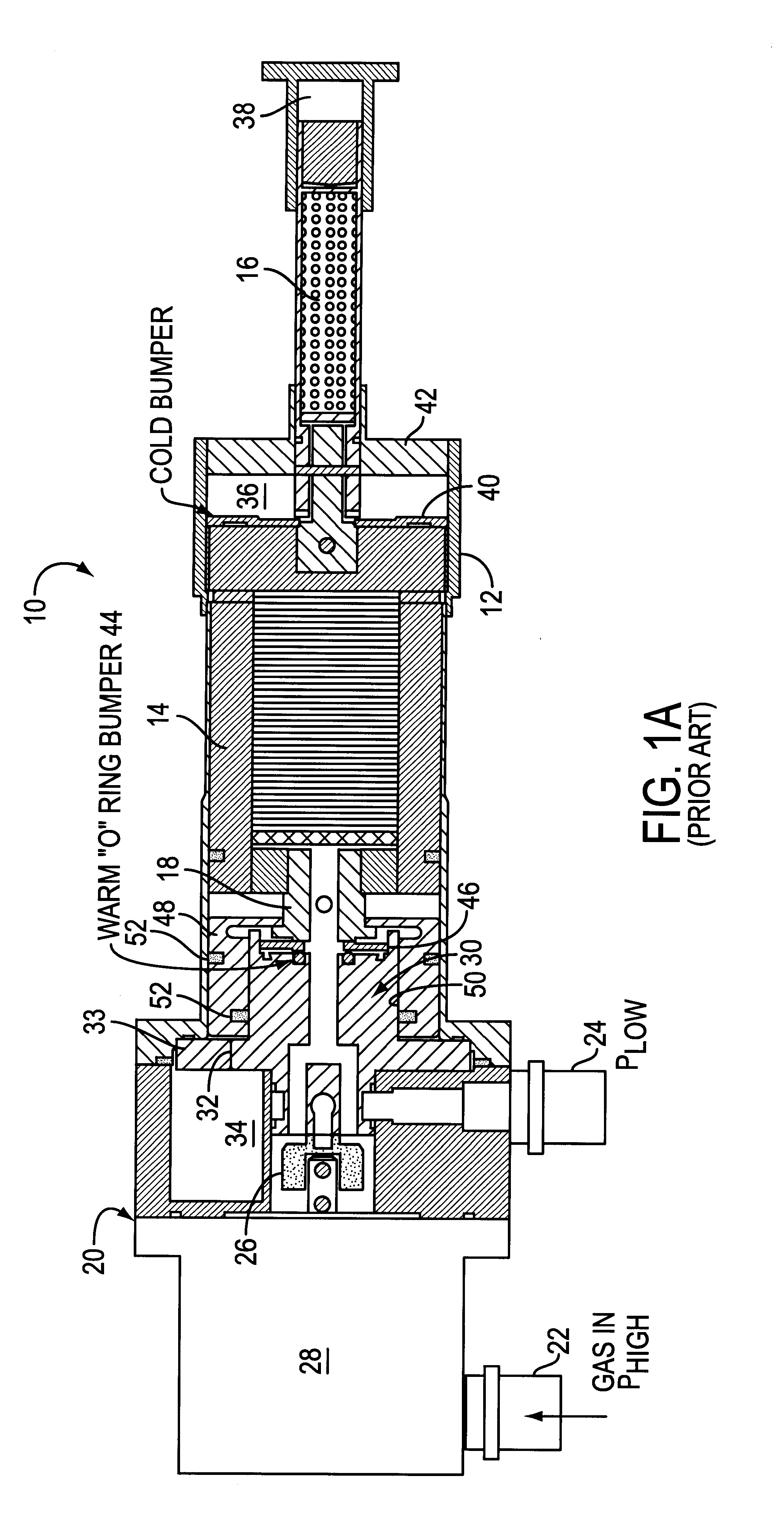
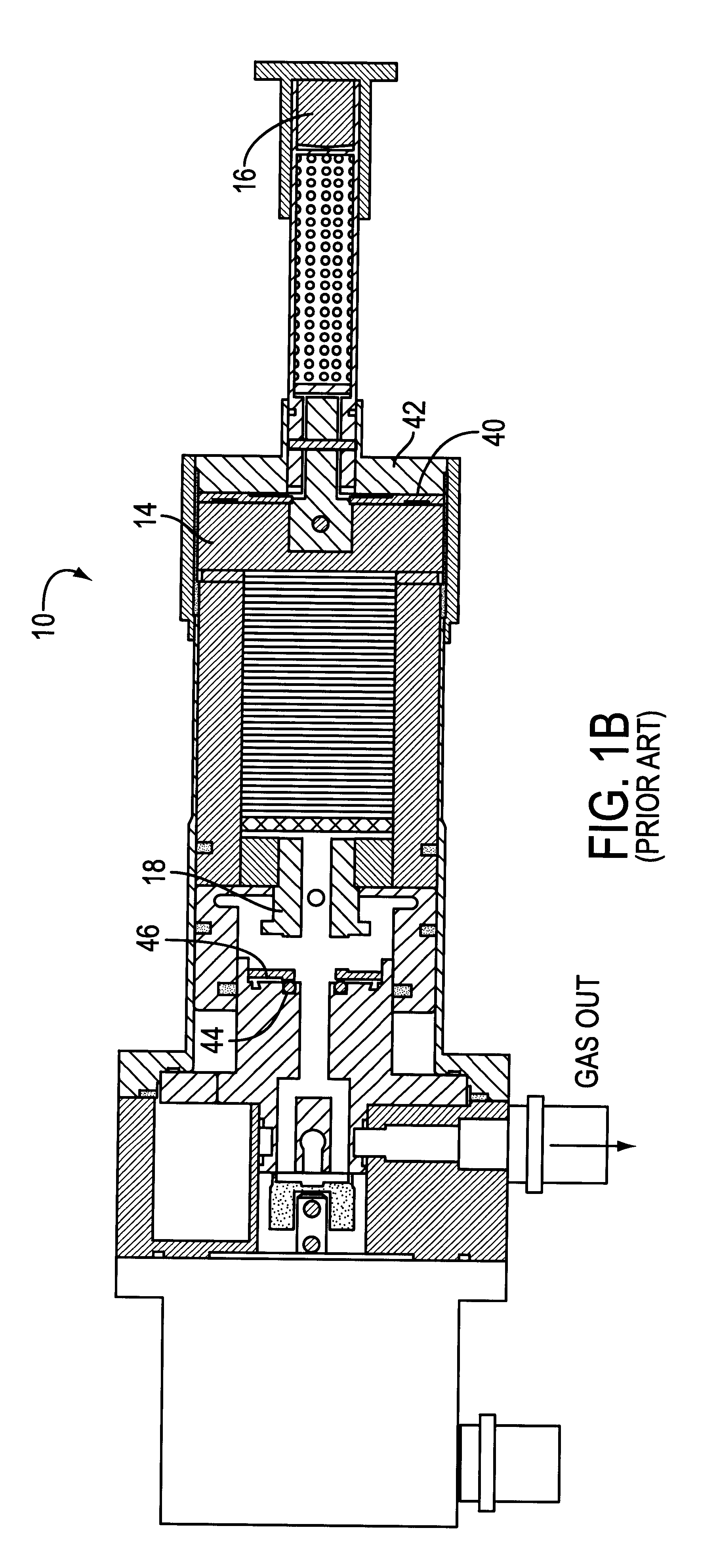
In the prior art (FIG. 1a), a two-stage pneumatically driven GM type expander 10 includes a circular cylinder assembly 12 of e.g. stainless steel, first stage displacer / regenerator 14, and second stage displacer / regenerator 16 connected together and mounted for reciprocal motion in the cylinder assembly 12, in a construction well known in the art.

Features of displacers / regenerators that are well known in the art and are not novel portions of the present invention, are not described in great detail herein.

A drive stem 18 fixedly connects, for example, by threading, to the first stage displacer / regenerator 14. A valve assembly 20 controls the flow of refrigerant gas, for example, helium, from an inlet 22 at elevated pressure to its outlet 24 at low pressure, and includes a rotary valve 26, valve motor 28, and valve stem 30. A fixed orifice 32 through a flange 33 of the valve stem 30 connects to a surge volume 34 that is within the valve assembly 20. The valve assembly 20 is fixedly c...


PUM


Abstract

A GM type displacer has an elastomer "O" ring at the warm end to absorb impact energy when the displacer reaches the bottom of the stroke before it would hit the cylinder end cap. When the displacer reaches the top of its stroke, before the displacer would hit the internal mechanism of the expander, another elastomer "O" ring absorbs the kinetic energy of the displacer. Both absorbers are at or near ambient temperature.

Description

BACKGROUND OF THE INVENTION:This application relates to vibration reduction in a GM displacer / regenerator, and more particularly, relates to vibration reduction in a pneumatically-driven GM displacer / regenerator. Cryogenic refrigerators of the GM type frequently include a multi-stage displacer / regenerator as a key element in expanding high pressure gaseous refrigerant to achieve extremely low temperatures.There is an abundance of prior art that describes various pneumatically-driven and mechanically-driven displacers and their operations in cryogenic systems and in achieving cryogenic temperatures. For example, basic principals of operation are described in the original Gifford-McMahon (GM) U.S. Pat. No. 2,906,101, issued Sep. 29, 1959. In that patent, which is incorporated herein by reference, the displacer is reciprocatingly driven in a cylinder by a conventional crank mechanism. Thus, low temperature refrigeration is effected with auxiliary equipment, such as connecting rods, cra...

Claims


Application Information

Patent Timeline
Patent Type & Authority Patents(United States)
IPC IPC(8): F25B9/14
CPCF25B9/14F25B2500/13F25B2309/006
Inventor LONGSWORTH, RALPH C.
Owner GENERAL ELECTRIC CO
Why Eureka
Try Eureka