Method for operating a discharge lamp

a discharge lamp and operation method technology, applied in the direction of electric discharge lamps, electric variable regulation, instruments, etc., can solve the problems of shift in the color locus of emitted light, the discharge lamp cannot be dimmed, etc., to achieve good dimmability of low-pressure discharge, high light yield, and high light yield

Inactive Publication Date: 2001-07-10
PATENT TREUHAND GESELLSCHAFT FUR ELECTRIC GLUEHLAMPEN MBH
View PDF6 Cites 12 Cited by
  • Summary
  • Abstract
  • Description
  • Claims
  • Application Information

AI Technical Summary

Benefits of technology

This mode of operation of the discharge lamp according to the invention unites with one another the high light yield of a dielectrically impeded discharge and the good dimmability of a low-pressure discharge. Since xenon gas is used as a discharge medium, it is predominantly ultraviolet radiation which is produced in the case both of the dielectrically impeded and the low-pressure discharges, which radiation is converted into white light or monochromatic light by fluorescent materials, with the result that it is possible to dispense with the addition of mercury in the discharge space. The color of the light emitted by the discharge lamp is determined only by the fluorescent materials. Consequently, the mode of operation according to the invention produces no color locus shifts by changing the electric power of the two types of discharge. It is advantageously only the dielectrically impeded discharge which is generated for the purpose of setting the undimmed operating state in the discharge lamp, since said discharge ensures a higher light yield than the dielectrically unimpeded discharge. In order to reduce the brightness, the electric power of the dielectrically impeded discharge is firstly advantageously reduced, and for the purpose of further reducing the brightness, the dielectrically impeded discharge is switched off and only the xenon low-pressure discharge is generated, the electric power of the xenon low-pressure discharge being set as a function of the desired brightness or dimming stage. The xenon low-pressure discharge can be dimmed to a substantially greater extent than the dielectrically impeded discharge, without having to fear extinction of the discharge or without the occurrence of an inhomogeneous discharge.

Problems solved by technology

This method does not permit dimming of the discharge lamp, since changes in the electric power of the two discharges lead to a shift in the color locus of the emitted light.

Method used


Image

  • Method for operating a discharge lamp
  • Method for operating a discharge lamp
  • Method for operating a discharge lamp

Examples


Embodiment Construction

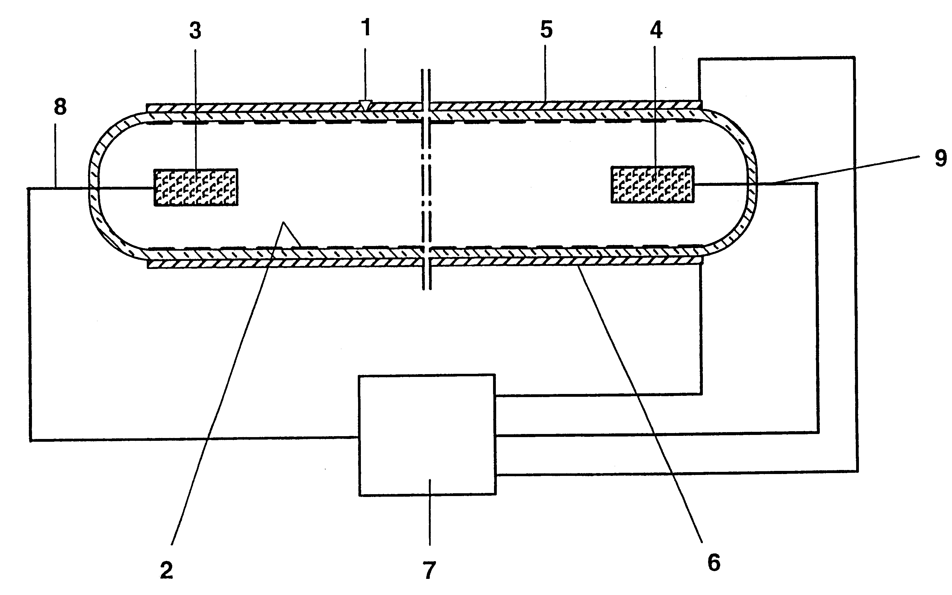
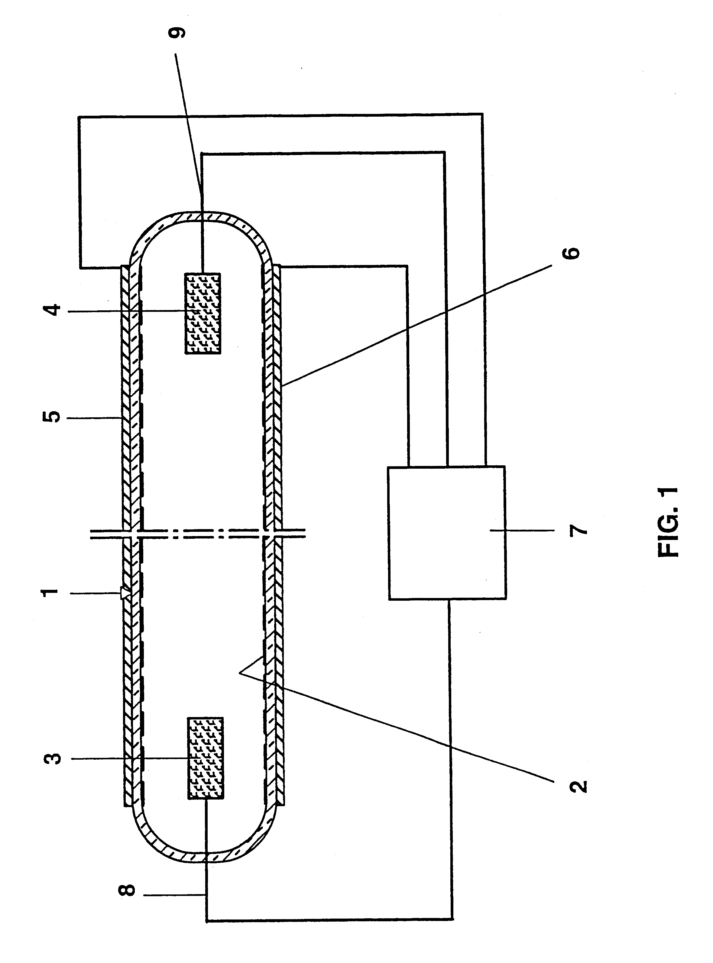
The invention is explained in more detail below with the aid of a preferred exemplary embodiment. FIG. 1 shows a schematic representation of a discharge lamp with the aid of which the method according to the invention is described in more detail. This discharge lamp serves, for example, as display back lighting for a display device in motor vehicles or aircraft.

The discharge lamp has a tubular glass discharge vessel 1 which is closed at the ends in a gastight fashion, has a length of approximately 160 mm and a diameter of approximately 9 mm and is coated on the inside with fluorescent material 2. The two ends of the discharge vessel 1 are fitted in each case with a cup-like cold cathode 3, 4 projecting into the interior of the discharge vessel 1. The cold cathodes 3, 4 are connected to an operating unit 7 by means of supply leads 8, 9 sealed in a gastight fashion in the ends of the discharge vessel 1. Two outer electrodes 5, 6 extending in the longitudinal direction and situated opp...


PUM


Abstract

An operating method, in particular a dimming method for a discharge lamp. In order to set the maximum brightness, two outer electrodes (5,6), for example, are used to generate in the discharge lamp a dielectrically impeded discharge which, through the formation of xenon excimers, emits UV radiation which is converted into light with the aid of fluorescent materials (2). In order to permit intense dimming of the discharge lamp, two cold cathodes (3, 4) are used to generate a xenon low-pressure discharge emitting UV beams, and the dielectrically impeded discharge is switched off. Both types of discharge are preferably excited by high-voltage pulses which are generated by an operating unit (7). Dimming is preferably performed by blanking pulse trains.

Description

The invention relates to a method for operating a discharge lamp in which a first dielectrically impeded discharge and a second dielectrically unimpeded discharge are generated in the discharge lamp.I. PRIOR ARTSuch a method is disclosed, for example, in laid-open patent application WO 96 / 36066. This publication describes an operating method for a discharge lamp in which a first, dielectrically impeded discharge and a second, dielectrically unimpeded discharge are generated in the discharge lamp. The dielectrically impeded discharge is superimposed on the dielectrically unimpeded discharge, or made to precede it temporally. The color locus of the light emitted by the discharge lamp is specifically set via the ratio of the electric powers of both discharges. Neon gas serves as discharge medium. The dielectrically impeded discharge generates neon excimers which emit as they decay UV radiation which is, in turn, converted into light by means of a fluorescent material, while the dielect...

Claims


Application Information

Patent Timeline
Patent Type & Authority Patents(United States)
IPC IPC(8): H01J65/04H01J61/00H01J61/16H01J61/12H01J61/78H01J61/92H05B41/24H01J65/00H05B41/392
CPCH01J61/16H01J65/046H01J61/92H01J61/78
Inventor DOELL, GERHARDRIEHL, HARTWIGENDERS, MARTIN
Owner PATENT TREUHAND GESELLSCHAFT FUR ELECTRIC GLUEHLAMPEN MBH
Why Eureka
Try Eureka