
Communication system architecture, infrastructure exchange and method of operation

Inactive Publication Date: 2001-07-17
RPX CLEARINGHOUSE
View PDF4 Cites 17 Cited by
  • Summary
  • Abstract
  • Description
  • Claims
  • Application Information

AI Technical Summary

Benefits of technology

Unfortunately, a significant cost in manufacturing infrastructure relates to the requirement to provide a plethora of modems (provided within line cards) to support the many subscriber terminals that operate within a broadband communication system. As such, it is desirable that the number of modems implemented within a system is minimised.
With respect to the structure of conventional telephony networks and particularly in relation to local telephone exchanges, a saving in each cost-to-customer connection is accomplished by reducing the number of switch-ports needed to service a given number of subscriber terminals. This concentration function is achieved by recognising that, although each subscriber terminal requires a connection to a central switch, the actual connection is discontinuous and bursty and therefore only carries traffic, i.e. information, for relatively short periods of time. As such, for a sufficiently large number of users, the number of switch-ports needed in the exchange is small in proportion to the number of subscriber terminals connected thereto.
According to a first aspect of the present invention, there is provided an infrastructure exchange responsive to a plurality of subscriber terminals each having a dedicated modem that supports data transmission, the infrastructure exchange comprising: at least one assignable modem capable of communicating with the dedicated modem of at least some of the plurality of subscriber terminals; and a first cross-point switch having a plurality of inputs and a plurality of outputs, the first cross-point switch arranged to route data transmission between the plurality of subscriber terminals and the at least one assignable modem; wherein the infrastructure exchange has fewer assignable modems than a combined number of dedicated modems in the plurality of subscriber terminals and the first cross-point switch acts to increase a ratio of dedicated modems in the plurality of subscriber terminals to assignable modems in the infrastructure exchange.
In a second aspect of the present invention there is provided a communication system comprising at least one exchange and a plurality of subscriber terminals each having a dedicated modem that supports data transmission, the infrastructure exchange comprising: at least one assignable modem capable of communicating with the dedicated modem of at least some of the plurality of subscriber terminals; and a first cross-point switch having a plurality of inputs and a plurality of outputs, the first cross-point switch arranged to route data transmission between the plurality of subscriber terminals and the at least one assignable modem; wherein the infrastructure exchange has fewer assignable modems than a combined number of dedicated modems in the plurality of subscriber terminals and the first cross-point switch acts to increase a ratio of dedicated modems in the plurality of subscriber terminals to assignable modems in the infrastructure exchange.
In another aspect of the present invention there is provided a method of transmitting data between a plurality of subscriber terminals each having a dedicated modem and at least one assignable modem of an infrastructure exchange, the at least one assignable modem capable of communicating with the dedicated modem of at least some of the plurality of subscriber terminals, the infrastructure exchange having a cross-point switch and fewer assignable modems than a combined number of dedicated modems in the plurality of subscriber terminals, the method comprising the step of: routing data between the plurality of subscriber terminals and the at least one assignable modem through the cross-point switch, thereby to increase a ratio of dedicated modems in the plurality of subscriber terminals to assignable modems in the infrastructure exchange.
The present invention therefore advantageously provides an ability to improve through a concentration function a ratio of dedicated subscriber-orientated modems to assignable modems located in an infrastructure exchange.

Problems solved by technology

Unfortunately, a significant cost in manufacturing infrastructure relates to the requirement to provide a plethora of modems (provided within line cards) to support the many subscriber terminals that operate within a broadband communication system.
However, appropriate dimensioning of the communication system will ensure that a redundancy is built into the communication system, and that switch-port contention (unavailability) only therefore happens very infrequently.
The broadband network cannot therefore provide simultaneous service to all broadband subscriber terminals, and yet broadband modems remain dedicated to a particular subscriber terminal regardless of its usage of the broadband service(s).
As previously stated, the provision of such dedicated modems on a per-line basis is expensive, and is further exaggerated by the increased complexity required in broadband networks.
Consequently, there is a significant increase in cost associated with providing a broadband network, which cost is over and above that for a corresponding narrowband telephony system and which therefore discourages wider deployment of broadband systems.
It is the complexity of the processor that contributes significantly to the cost of each modem, with this complexity increasing as a function of the number of services (and the information bearing capabilities of each service) supported in the broadband network.
Indeed, in relation to broadband communication, generally, types of transmission technology range from simple coding schemes (that are suitable for short distances) to elaborate and complex signalling schemes that achieve greater distance penetration over a communication resource, such as a twisted pair.
These more elaborate and complex signalling schemes therefore necessarily require greater processing capabilities and consequently impose additional costs, although very large scale integration can eliminate the necessity for some dedicated, high cost modems.

Method used


Image

  • Communication system architecture, infrastructure exchange and method of operation
  • Communication system architecture, infrastructure exchange and method of operation
  • Communication system architecture, infrastructure exchange and method of operation

Examples


Embodiment Construction

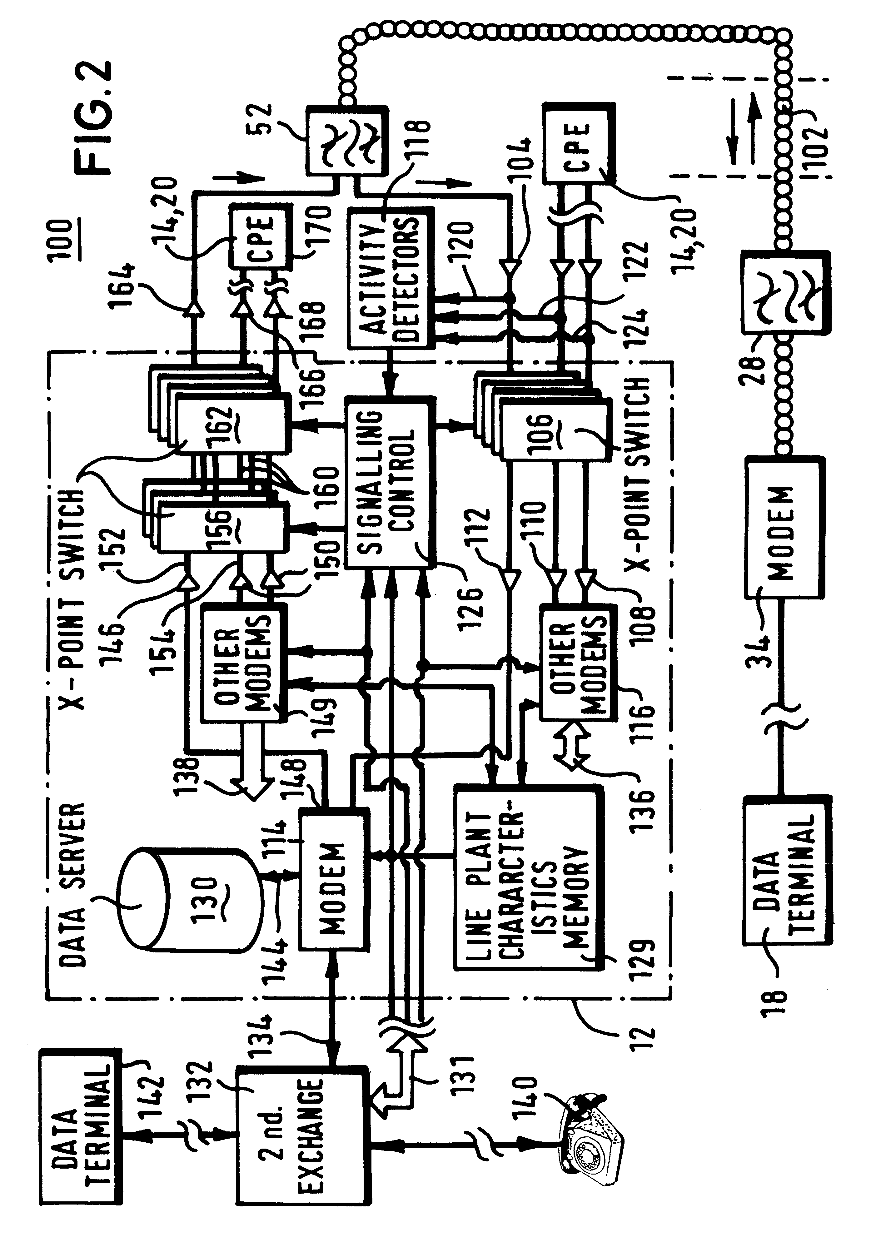
Before discussing a preferred embodiment of the present invention in detail, a comprehensive discussion of a prior art, wire-line communication network 10 (of FIG. 1) will be presented. The wire-line communication network 10 comprises an exchange 12 that is coupled, via twisted pairs 22-24, to a plurality of subscriber terminals 14-20, such as telephones and computers (generically termed "customer premises equipment"). More particularly, the customer premises equipment will be coupled to the twisted pairs 22-24 through filters 26-28 that provide frequency separation and isolation of voice and data communications, for example. More importantly, the filters 26-28 allow spare spectrum (i.e. a spare frequency channel) on a communication resource to be utilised by providing a separation of broadband signalling from conventionally encoded voice signals. with the broadband transmissions supported by techniques such as asynchronous digital subscriber line signalling (ADSL), high speed digit...


PUM


Abstract

An infrastructure exchange (12) has a cross-point switch that is arranged to couple data transmission between subscriber terminals (16, 18), each having a dedicated modem (34), and at least one assignable modem (148) located in the infrastructure exchange (12). The infrastructure exchange (12) comprises fewer assignable modems than a combined number of dedicated modems within the subscriber terminals (16, 18) and, since the cross-point switch (106) is responsive to the data transmission sent via the modems of the subscriber terminals, the cross-point switch (106) thereby acts to concentrate a ratio of dedicated modems to assignable modems.

Description

BACKGROUND TO THE INVENTIONThis invention relates, in general, to the architecture of a communication system, and is particularly, but not exclusively, applicable to an arrangement of modems in an exchange of a telephone network, such as a public switched telephone network (PSTN).SUMMARY OF THE PRIOR ARTTelecommunication systems that interconnect subscriber terminals are now capable of supporting broadband data communication on both an inter-subscriber terminal basis (through an exchange) or on a client-server to subscriber terminal basis. In either case, both the subscriber terminal and the infrastructure equipment contain a dedicated modem, which modems are coupled together to support communication between the subscriber terminal and the exchange. In this respect, there is a one-to-one mapping between modems associated with each subscriber terminal and the infrastructure. For example, current broadband access systems that interconnect subscriber terminals and an exchange use coppe...

Claims


Application Information

Patent Timeline
IPC IPC(8): H04M11/06H04Q11/04
CPCH04M11/06H04M11/062H04Q11/04H04Q2213/1302H04Q2213/1304H04Q2213/1309H04Q2213/13386H04Q2213/13174H04Q2213/13176H04Q2213/13199H04Q2213/1332H04Q2213/13332H04Q2213/13103
Inventor DYKE, PETER JOHNUNITT, BRIAN MICHAELLEWIS, ANDREW PAUL
Owner RPX CLEARINGHOUSE
Features
  • Generate Ideas
  • Intellectual Property
  • Life Sciences
  • Materials
  • Tech Scout
  • Unparalleled Data Quality
  • Higher Quality Content
  • 60% Fewer Hallucinations
Learn More