
Method and system for determining oil quality

a technology of oil quality and method, applied in the field of methods, can solve the problems of significant influence on the performance of oil, increase the conductivity of oil, and increase measurement errors, so as to minimize contaminant buildup and determine oil quality quickly

Inactive Publication Date: 2001-07-31
DETROIT DIESEL CORP
View PDF16 Cites 53 Cited by
  • Summary
  • Abstract
  • Description
  • Claims
  • Application Information

AI Technical Summary

Benefits of technology

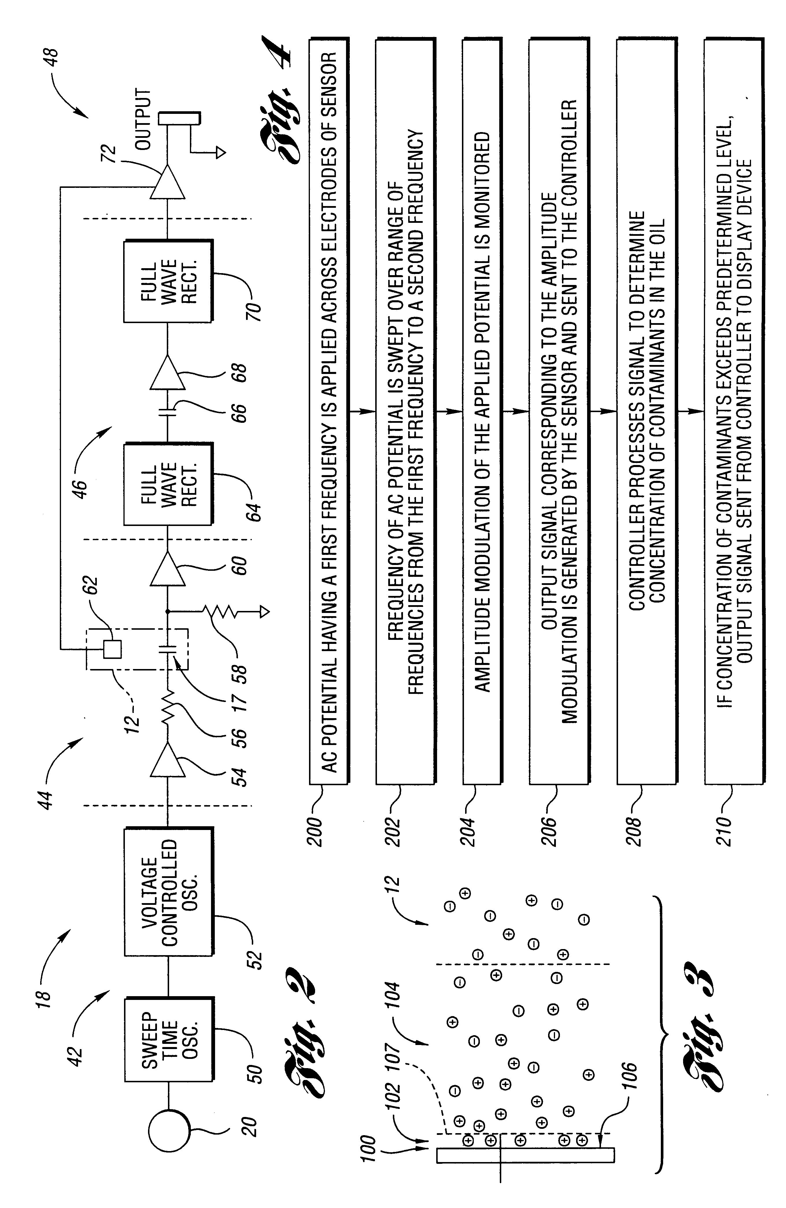
Advantageously, because error capacitance is frequency dependent, the effects of error capacitance can be determined by varying the frequency of the applied potential. Furthermore, because error capacitance is related to the concentration of contaminants in the oil, oil quality can be quickly determined by evaluating error capacitance.
Preferably, the method also includes electrically insulating at least one of the electrodes from the oil to inhibit current from passing from the electrode through the oil. Furthermore, the applied potential is preferably symmetrically balanced so as to minimize contaminant buildup on one or both of the electrodes.

Problems solved by technology

The presence of contaminants in the oil, however, significantly affects the performance of the oil.
Such contaminants include soot, dissolved gases, dissolved liquids, emulsified liquids, and particles resulting from system wear.
While the capacitive reactance can be measured with little error in non-polar oil, measurement error increases with increasing conductivity of the oil due to solution current flowing through the oil.
Many of these additives, however, are polar and increase the conductivity of the oil.
Solution current also increases as contaminants increase in the oil during use.
Furthermore, prior art methods and systems typically utilize an unbalanced alternating current (AC) or static direct current (DC) potential that causes migration of polar contaminants toward oppositely charged sensor electrodes.
Eventually, this contaminant migration results in build up of contaminants on the electrodes, which contributes to erroneous capacitive reactance measurements of the oil.
A prior approach to reduce contaminant buildup has been to coat one or both of the electrodes with a non-stick surface such as TEFLON.RTM.. This approach, however, does not reduce polar contaminant migration toward the electrodes.

Method used


Image

  • Method and system for determining oil quality
  • Method and system for determining oil quality
  • Method and system for determining oil quality

Examples


Embodiment Construction

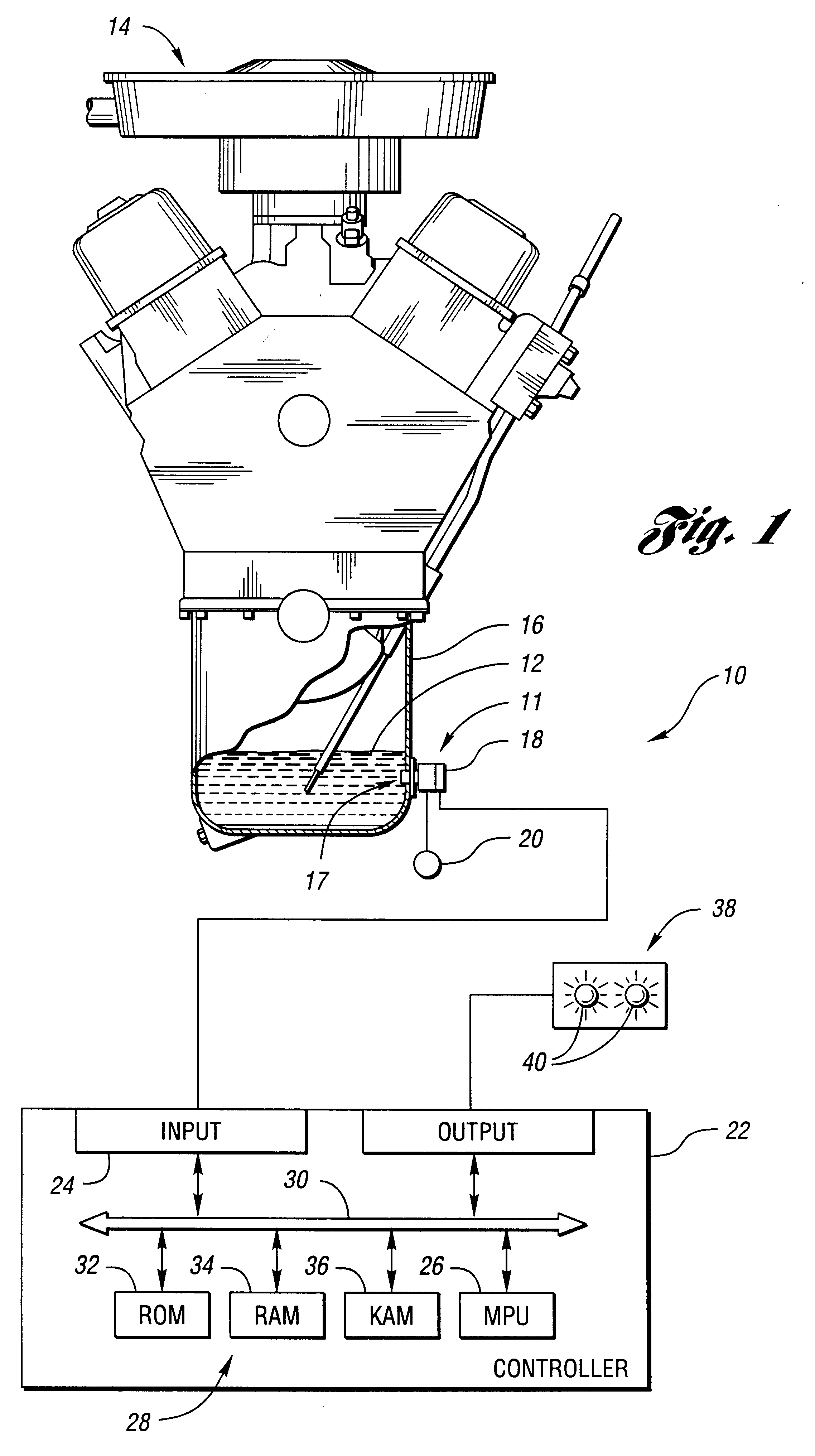
FIG. 1 shows a system 10 according to the invention for determining quality of lubricating oil 12 in a motor vehicle engine 14, or other suitable arrangement such as a compressor, pump or gear box. The system 10 includes a sensor 11 adapted to be mounted to an oil reservoir 16 of the engine 14. The sensor 11 has two spaced electrodes 17 adapted to be immersed in the oil 12, and a control circuit 18. When the electrodes 17 are joined by the oil 12, which is generally a dielectric material, a capacitor is formed.

As further shown in FIG. 1, the sensor 11 is connected to a power source 20. The power source 20, in combination with the control circuit 18, is used to apply a time-varying potential, such as an AC potential, across the electrodes 17. The power source 20 may, for example, include a motor vehicle battery and a DC to DC converter for providing regulated positive and negative voltages to the control circuit 18. Preferably, the power source 20 and the control circuit 18 cooperate...


PUM


Abstract

A method for determining quality of lubricating oil includes positioning first and second electrodes in the oil, wherein the electrodes are coated with an electrically insulating material; applying a symmetrically balanced time-varying potential to the electrodes, the potential having a predetermined amplitude; sweeping the potential over a range of frequencies from a first frequency to a second frequency greater than the first frequency; monitoring magnitude of amplitude modulation of the potential over the range of frequencies; and determining the quality of the oil based on variation of the amplitude modulation. A system for practicing the method is also provided.

Description

The invention relates to a method and system for accurately determining oil quality, wherein the method and system involve applying a potential across two electrodes disposed in the oil, and varying frequency of the potential over a range of frequencies.Lubricating oil improves the efficiency and durability of such systems as internal combustion engines, compressors, pumps and gear boxes. The presence of contaminants in the oil, however, significantly affects the performance of the oil. Such contaminants include soot, dissolved gases, dissolved liquids, emulsified liquids, and particles resulting from system wear.Many methods and systems have been developed to detect contaminants in oil. One prior system, for example, includes a capacitive oil deterioration sensor that is used to determine the dielectric constant of engine oil based on the capacitive reactance of the oil. The theory behind this sensor is that the dielectric constant of the oil is related to the concentration of cont...

Claims


Application Information

Patent Timeline
IPC IPC(8): G01N27/22G01N33/28G01N33/26
CPCG01N33/2888G01N27/221
Inventor MARSZALEK, GARY A.
Owner DETROIT DIESEL CORP
Learn More