Reinforcing carbon fiber material, laminate and detecting method

a technology of reinforced carbon fiber and carbon fiber material, which is applied in the direction of natural mineral layered products, water-setting substance layered products, using mechanical means, etc., can solve the problems of cracks in concrete, major accidents, and widened cracks in concr

Inactive Publication Date: 2001-08-21
TORAY IND INC
View PDF0 Cites 72 Cited by
  • Summary
  • Abstract
  • Description
  • Claims
  • Application Information

AI Technical Summary

Problems solved by technology

Concrete structures include floor slabs, bridge piers, tunnels and buildings, but there occurs rusting of the internal reinforcements due to neutralization of the concrete and salt damage, and deterioration due to the alkali aggregate reaction, and these constitute problems for society.
Again, when vibration due to passing traffic or due to earthquakes, and the pressure of earth and sand in the case of a tunnel, are also added, the cracks which occur in the concrete are widened and the progress of deterioration hastened.
Moreover, since structures in the civil engineering and construction fields are often of a large size, it is not possible to predict rupture and there is the possibility of a major accident arising due to sudden failure.
However, non-destructive inspection such as direct observation is mainly employed at present, and it is not easy to ascertain the state of fatigue or deterioration correctly.
However, since they detect strain within their own area and, moreover, since their length is short at no more than 30 mm, they can only detect local strain.
Hence, the extent of filament failure under an identical load will differ according to the particular yarn, and the reproducibility of changes in electrical resistance in these yarns is poor.
Furthermore, with regard to the terminals at the two ends of the yarns where resistance measurement is required, it is necessary that there be contact with all the individual filaments, but it is difficult to effect contact with all the thousands or tens of thousands of filaments of diameter just a few microns within the yarn.
Consequently, the arrangement of the metal wire is a complex procedure which is carried out by hand on the reinforcing fiber base material while the resin remains uncured immediately after the impregnation.
By such a method of arrangement, very often the metal wire is not arranged parallel to the reinforcing wire but meanders, so strain in the FRP which has been designed based on loads and strain in the reinforcing fiber direction is not accurately detected from said metal wire.
However, the setting of the lamination direction and the number of plies of sheet-shaped carbon fiber base material in the laminate is carried out manually, so there is the possibility of mistakes being made.
Moreover, in the case where repair or reinforcement of a concrete structure is carried out by affixing sheet-shaped carbon fiber base material to the structure, then impregnating with a cold-curing type epoxy resin and curing, the checking of the number of plies in the laminate of sheet-shaped base material is carried out for example by the method of taking photographs following the completion of the layup of each single layer, but this is extremely troublesome.

Method used


Image

  • Reinforcing carbon fiber material, laminate and detecting method
  • Reinforcing carbon fiber material, laminate and detecting method
  • Reinforcing carbon fiber material, laminate and detecting method

Examples


example 2

(EXAMPLE 2)

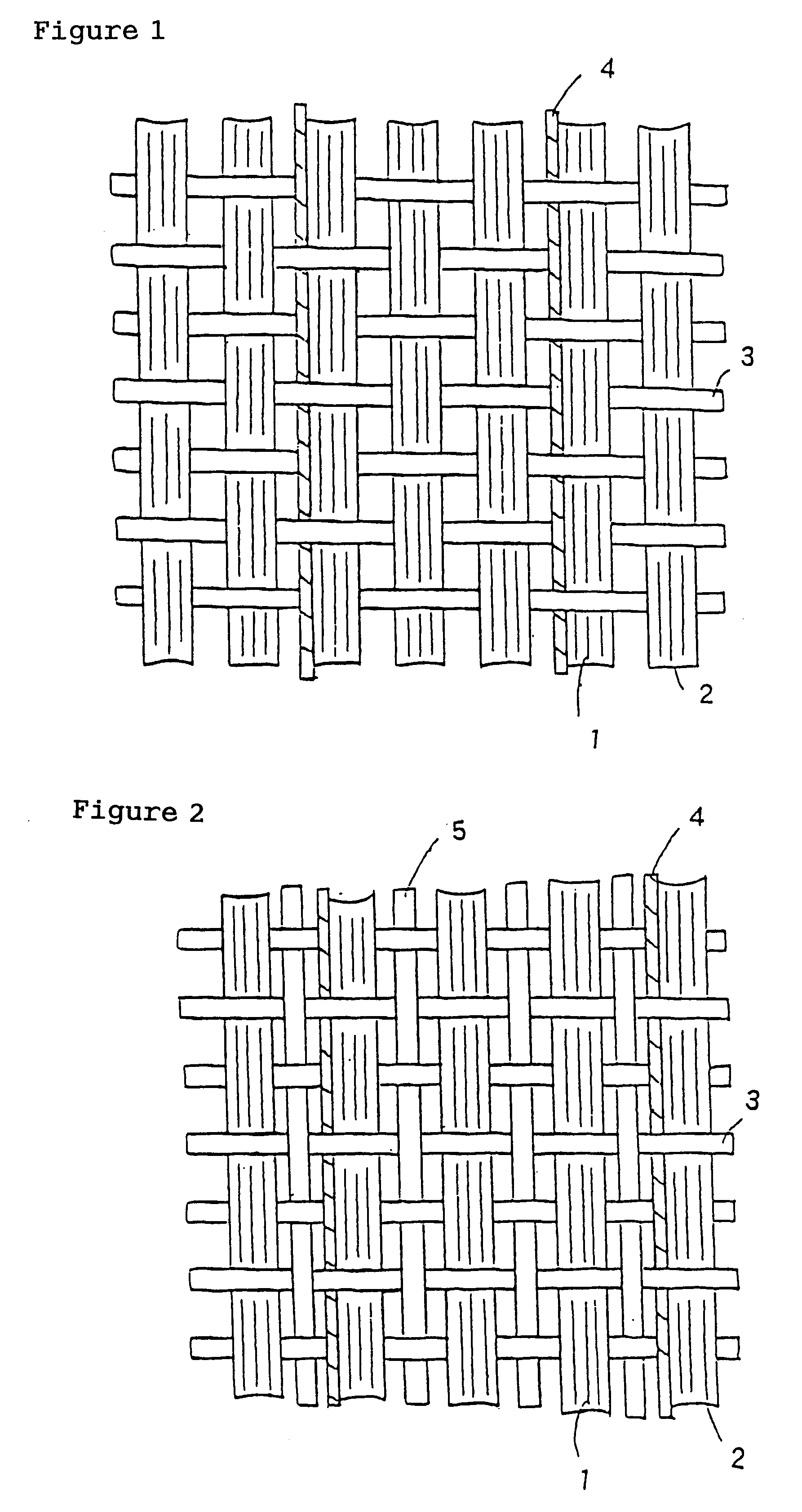
Excepting that there was employed the woven fabric shown in FIG. 5 in which the arrangement direction of the metal wire was in the weft direction, the production of a CFRP and the evaluation thereof were carried out in the same way as in Example 1. The results are shown in Table 2.

With regard to the arrangement of the metal wire in the widthwise direction here, this was carried out by insertion along with some of the glass fiber when introducing the weft glass fiber at the time of the construction of the woven fabric.

No difference in the graphs of strain against electrical resistance was noted before and after the fatigue testing, and by applying 0.2% strain the resistance was increased by 0.12 .OMEGA..

When the arrangement direction of the nichrome wire within the test piece was determined in the same way as in Example 1, since it was interwoven in the form of weft, no meandering or the like was observed.

example 3

(EXAMPLE 3)

As the metal wire, there was employed iron wire of diameter 0.11 mm, and by covering this wire by winding 75 denier, 36 filament, multifilament polyester yarn in the S direction and then 100 denier low-melting nylon yarn in the Z direction at 1000 turns per metre, there was prepared insulation-covered iron wire of covering ratio 100%.

Next, PAN-based high strength carbon fiber (number of filaments: 24,000; 14,400 denier; tensile strength 4900 MPa, tensile elastic modulus 230 GPa) was arranged at a density of 1.88 yarns per cm in the lengthwise direction, and in the widthwise direction there was introduced as auxiliary yarn, at a density of 3 yarns per cm, covered yarn produced by covering 405 denier glass fiber with 50 denier low-melting nylon yarn. At a 50 cm spacing, instead of two picks of the auxiliary yarn there was arranged the aforesaid covered iron wires two-together, so that a total of four iron wires was inserted. Next, by heating with a heater, the low-melting n...

example 4

(EXAMPLE 4)

Using an identical laminate to that in Example 4, the electric wires were heated for 1 minute using a 100 V, 1400 W electromagnetic induction device, after which this electromagnetic induction device was removed and measurement performed with an infrared radiation thermometer set at a distance of 1 m from the laminate. Now, as the infrared radiation thermometer there was used one with a HgCdTe detector, having a minimum detectable temperature difference at 30.degree. C. of 0.08.degree. C. and of measurement range -50 to 2000.degree. C.

When the temperature distribution was displayed as a colour thermal image, four regions of high temperature were observed of long thin shape running in the bridge pier lengthwise direction and it was possible to detect the fact that the number of plies was four.


PUM

PropertyMeasurementUnit
volume fractionaaaaaaaaaa
lengthaaaaaaaaaa
lengthaaaaaaaaaa

Abstract

A sheet-shaped carbon fiber base material is made up from reinforcing carbon fiber and metal wire integrally formed into a carbon fiber base material which may be a a woven fabric, a tow sheet and a prepreg. The volume fraction of metal in the sheet-shaped reinforcing carbon fiber base material is no more than 4% of the carbon fiber. A laminate may also be formed from the sheet-shaped carbon fiber material, where the reinforcing carbon fiber and the metal wire are laid-up in such a way that the metal wire insertion positions are mutually different. Also disclosed is a method of detecting the number of plies in a laminate that includes non-destructively sensing with a detector the presence of metal wire in a laminate of plies of a sheet-shaped carbon fiber base material made up of reinforcing carbon fiber and metal wire integrally formed to make the sheet-shaped carbon fiber laminate material and determining the number of the plies in the laminate based on the metal wires detected.

Description

The present invention relates to a reinforcing carbon fiber base material for obtaining FRP (fiber reinforced plastic) which is used as a structure or together with a structure; to a laminate thereof; to a method for detecting strain or deterioration arising in structures using same; and to a method for detecting the number of plies in the laminate.TECHNICAL BACKGROUNDIn recent years, the applications of FRPs have broadened and they have begun to be widely applied not just in the aerospace and sports fields but also to large-size structures in fields such as civil engineering and construction.In particular, the use of FRPs in the repair or reinforcement of concrete structures is the subject of attention and is increasing for reasons such as the easing of vehicle weight restrictions, the occurrence of major earthquakes and the ease of use of such FRPs. Concrete structures include floor slabs, bridge piers, tunnels and buildings, but there occurs rusting of the internal reinforcements...

Claims


Application Information

Patent Timeline
Patent Type & Authority Patents(United States)
IPC IPC(8): D03D15/00D03D15/02B29C70/22B29C70/88
CPCB29C70/22D03D15/00D03D15/02D03D9/00D03D15/0011D03D15/0088B29C70/885Y10T428/294B29K2305/02B29K2305/10B29K2305/12B29K2305/14B29K2901/10D10B2101/12D10B2101/20D10B2505/02D10B2101/06D10B2321/022D10B2331/021D10B2331/04D10B2401/062D10B2401/063D10B2401/16Y10T428/2915Y10T428/2933Y10T428/30Y10T428/29Y10T428/2913Y10T442/361Y10T442/339D03D15/46D03D15/267D03D15/275D03D15/573D03D15/67B32B5/00
Inventor NISHIMURA, AKIRAKOBAYASHI, TAKASHIHORIBE, IKUOHOMMA, KIYOSHI
Owner TORAY IND INC
Why Eureka
Try Eureka