Cube corner cavity based retroeflectors with transparent fill material

a retroeflector and cube corner cavity technology, applied in the field of radiation cureable materials, can solve the problems of undesirable filling, essentially nullifying the last advantage, and undesirable filling, and achieve the effects of reducing cost, good flexibility of sheeting articles, and maintaining functionality and durability

Inactive Publication Date: 2001-08-28
3M INNOVATIVE PROPERTIES CO
View PDF39 Cites 87 Cited by
  • Summary
  • Abstract
  • Description
  • Claims
  • Application Information

AI Technical Summary

Benefits of technology

Retroreflective articles are disclosed having a body layer with a structured surface in which recessed faces define cube corner cavities. A transparent adhesive material fills the cube corner cavities. The adhesive material is preferably a pressure-sensitive adhesive. In one embodiment, a release liner covers the fill material. In another embodiment, a transparent cover layer takes the place of the release liner. The cover layer adds durability to the article, and can also incorporate dyes, colorants, or the like to affect the appearance of the sheeting or to convey information.
To reduce cost while maintaining functionality and durability, the constructions preferably utilize thermoplastic materials for the body layer and the cover layer. Good flexibility of sheeting articles can be aided by the use of fill materials whose elastic modulus after crosslinking is less than about 50,000 psi (345.times.10.sup.6 Pascals), and preferably less than about 25,000 psi (172 MPa).

Problems solved by technology

Unfortunately, this latter advantage can be essentially nullified in constructions where the cube corner cavities in the body layer are filled with a transparent substance.
But such filling is undesirable insofar as it requires forcing material into an array of closed cavities.
Such filling is also undesirable to the extent it exposes the body layer to excessive heat, mechanical stress, or other process conditions that could compromise the fidelity of the structured surface.

Method used


Image

  • Cube corner cavity based retroeflectors with transparent fill material
  • Cube corner cavity based retroeflectors with transparent fill material
  • Cube corner cavity based retroeflectors with transparent fill material

Examples


examples 1-4

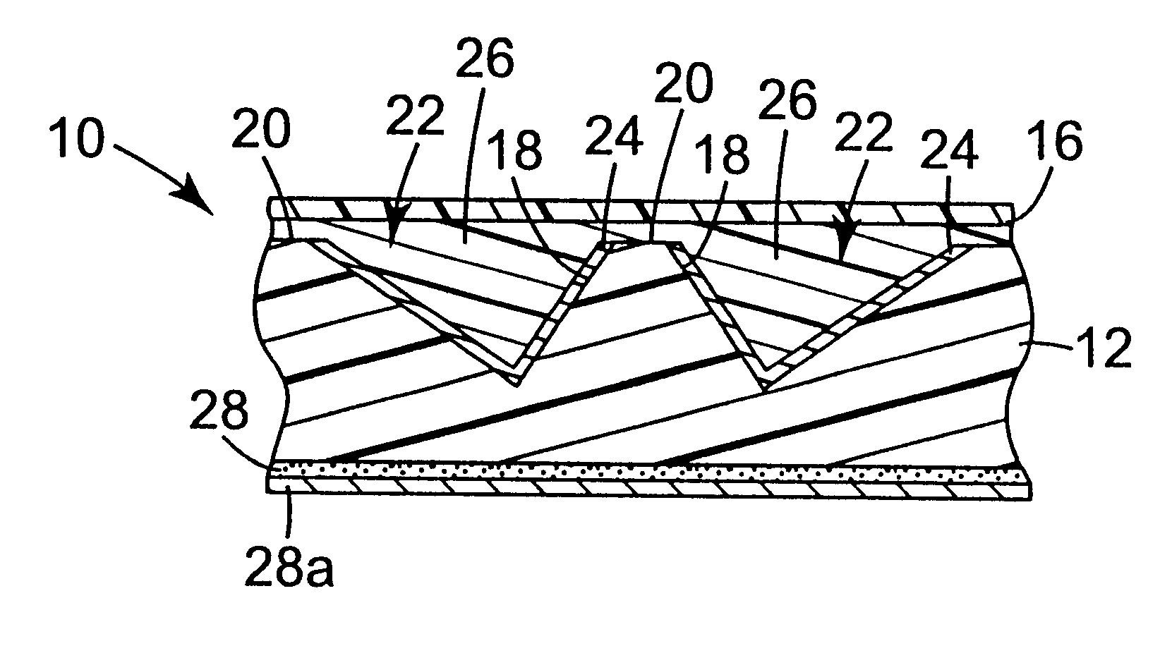
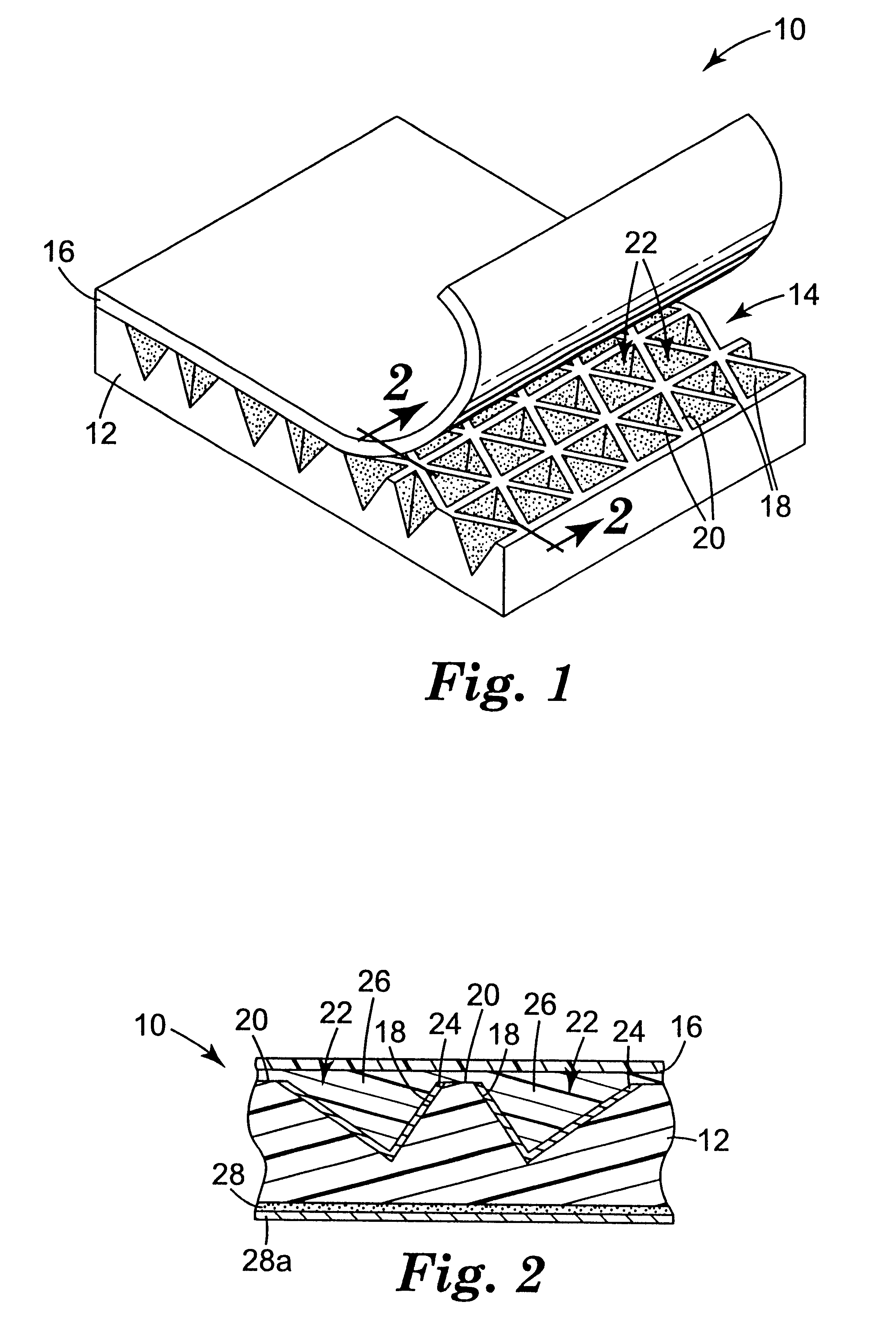
Four body layers were embossed with a mold to impart a structured surface similar to that shown in FIG. 1. The mold had a structured surface consisting of three sets of flat-bottomed grooves, and was the negative replica of a prior mold whose upper portions had been ground down flat with an abrasive. The embossed body layers were made of polycarbonate. The body layers for Examples 1 and 2 had a thickness of about 43 mils (1.1 mm) and included sufficient TiO.sub.2 filler to make them opaque with a diffuse white surface appearance. Those for Examples 3 and 4 had a thickness of about 18 mils (0.46 mm) and included instead a red dye to give a diffuse red surface appearance. The structured surface of each body layer consisted essentially of three intersecting sets of parallel ridges. Two of the sets, referred to as "secondary" ridge sets, had uniform ridge spacings of about 16 mils (408 .mu.m) and intersected each other at an included angle of about 70 degrees. The other set of parallel ...

examples 5-16

Twelve body layers made of polystyrene (type 498 Styron brand, available from Dow Chemical Co., Midland, Mich.) were embossed with a mold to impart a structured surface consisting essentially of three intersecting sets of parallel ridges. Six of the body layers (Examples 5-10) were natural, clear polystyrene and the remaining six (Examples 11-16) used polystyrene compounded with a titanium dioxide concentrate to impart diffuse whiteness. The body layers were each about 9 mils (230 .mu.m) thick. Two of the three sets of parallel ridges, referred to as "secondary" ridge sets, had uniform ridge spacings of about 5.74 mils (146 .mu.m) and intersected each other at an included angle of about 70 degrees. The other set of parallel ridges, referred to as the "primary" ridge set, had a uniform ridge spacing of about 5 mils (127 .mu.m) and intersected each of the secondary ridge sets at an included angle of about 55 degrees. This produced cube corner cavity matched pairs having a cavity depth...

example 17

A roll of body layer retroreflective sheeting substantially the same as those of Examples 5-16 was prepared. The same structured surface geometry and reflective aluminum film was used.

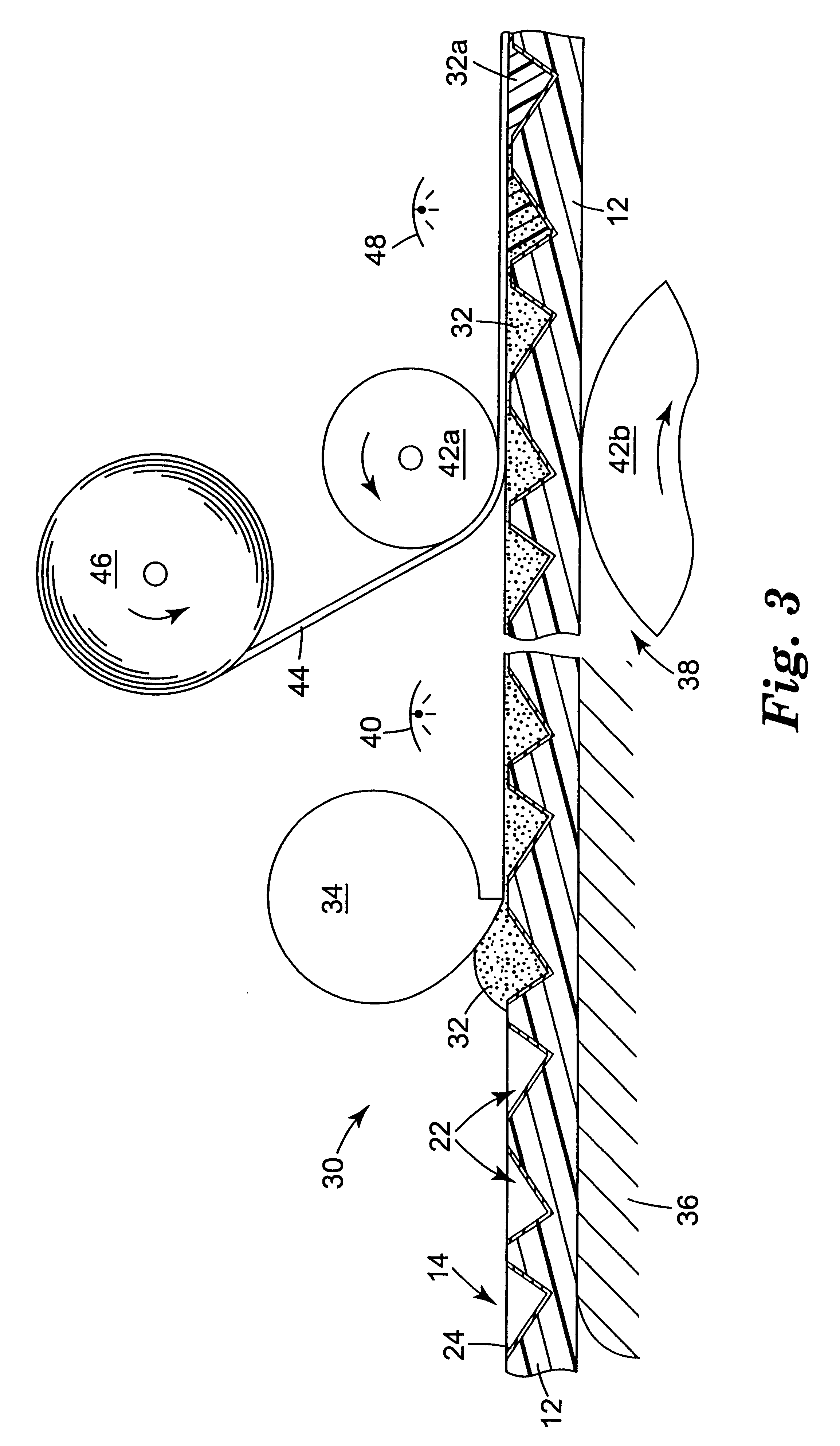
A pressure-sensitive adhesive resin composition was prepared by mixing 75 parts of isooctyl acrylate and 25 parts of N-vinylcaprolactam to yield about 2000 grams. Then 0.05 pph of a photoinitiator (2,4,6-trimethylbenzoyldiphenylphosphine available as Lucirin.TM. TPO from BASF Corp.) was added. Nitrogen was bubbled through the composition and the composition was exposed to Sylvania black lights to partially polymerize it to a viscosity of about 1700 centipoise (1.7 Pa-s). The composition viscosity was measured using a model LVF Brookfield Viscometer equipped with a number 4 spindle at 60 rpm at room temperature. In the partial polymerization process, the temperature of the composition increased from 23.degree. C. to about 38.degree. C. The composition was then sparged with air and cooled to room tempera...


PUM

PropertyMeasurementUnit
elastic modulusaaaaaaaaaa

Abstract

Retroreflective sheeting includes a body layer having a structured surface with recessed faces forming cube corner cavities. A reflective film is disposed at least on the recessed faces, and a fill material fills the cube corner cavities. The fill material comprises radiation-curable materials, adhesives, or both, and preferably transparent radiation-curable pressure-sensitive adhesives. The fill material preferably forms a continuous layer covering both the recessed faces and upper portions of the structured surface. A transparent cover layer preferably contacts the fill material layer.

Description

The present invention relates to U.S. application Ser. No. 09 / 227,963, "Cube Corner Cavity Based Retroreflectors and Methods For Making Same", filed on even date herewith and incorporated by reference.The present invention relates generally to retroreflective articles such as sheeting. More particularly, the invention relates to such articles or sheetings in which retroreflective elements comprise reflective faces arranged to form a cavity.The reader is directed to the glossary at the end of the specification for guidance on the meaning of certain terms used herein.Cube corner retroreflective sheetings can generally be categorized as those that use a rear-surface body layer and those that use a front-surface body layer. Commercially available cube corner retroreflective sheetings are of the former type, in which a thin transparent body layer has a substantially planar front surface and a rear structured surface comprising a plurality of geometric structures of pyramidal shape, some ...

Claims


Application Information

Patent Timeline
Patent Type & Authority Patents(United States)
IPC IPC(8): G02B5/124G02B5/12B32B7/02
CPCB29D11/00605G02B5/124Y10S428/913Y10T428/24612Y10T428/24521Y10T428/1471Y10T428/24545Y10T428/14Y10T428/1476
Inventor SMITH, KENNETH L.BENSON, GERALD M.CODERRE, JAMES C.FREY, CHERYL M.WILSON, BRUCE B.CRATON, MICHELE A.DANIELS, MICHAEL P.LUEHRS, ROGER E.
Owner 3M INNOVATIVE PROPERTIES CO
Why Eureka
Try Eureka