
Amplifier with improved, high precision, high speed and low power consumption architecture

a technology of high speed and low power consumption, applied in the direction of dc-amplifiers with dc-coupled stages, amplifiers with semiconductor devices/discharge tubes, different amplifiers, etc., can solve the practical limit set by power consumption and dc-ac precision requirements, poor slew-rate performance, and low dc and ac precision

Inactive Publication Date: 2001-08-28
INFINEON TECH AG
View PDF5 Cites 9 Cited by
  • Summary
  • Abstract
  • Description
  • Claims
  • Application Information

AI Technical Summary

Problems solved by technology

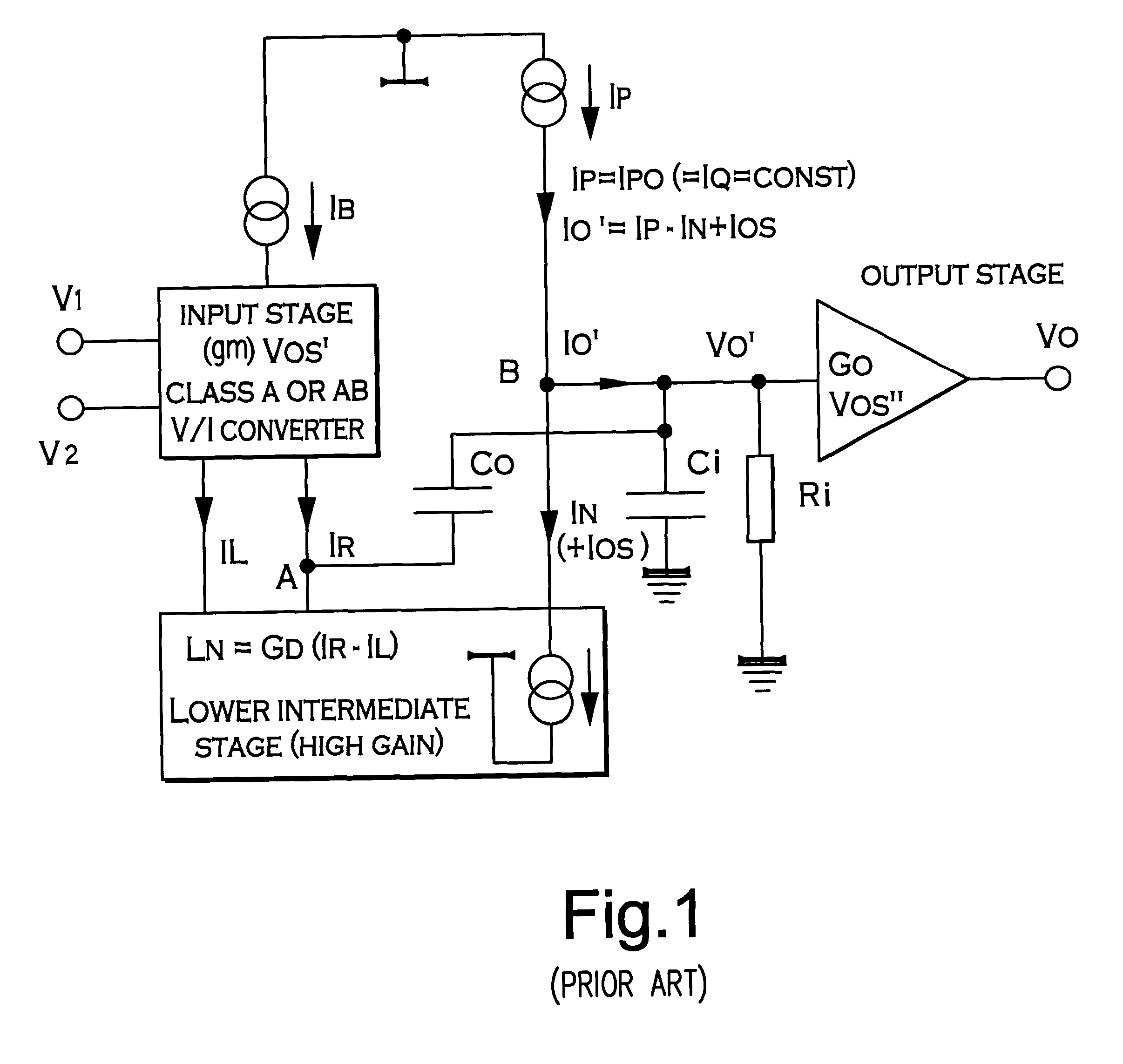
Resuming, the advantages of conventional amplifier architectures of FIG. 1, may be summarised as a high DC open loop gain, a low noise and a high DC precision; the disadvantages as poor slew-rate performances, which are determined by the class A input stage, then in the poor width of power band, wherein f.sub.max =SR / 2V.sub.peak.
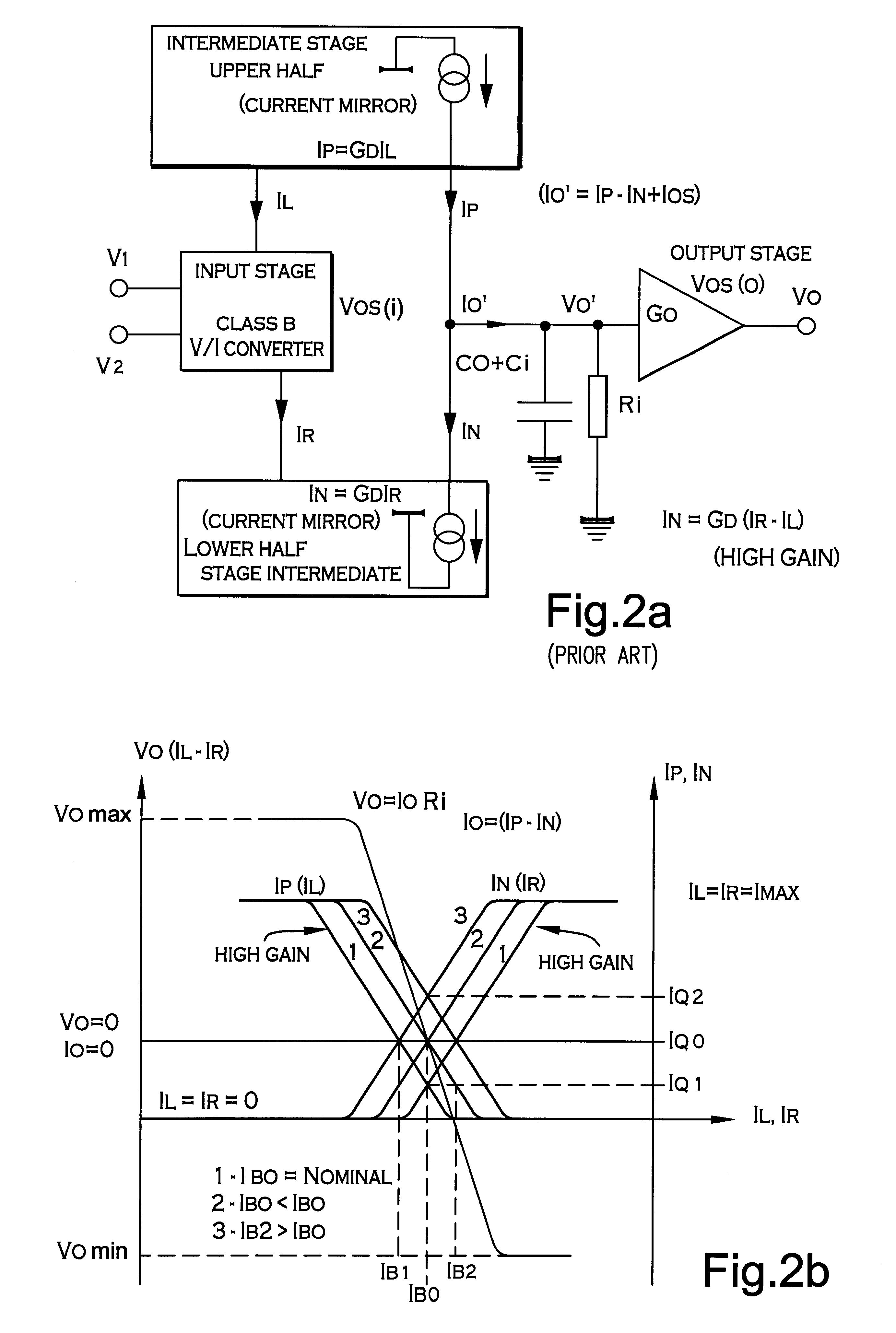
Slew rate can be increased only by increasing I.sub.P =I.sub.PO =I.sub.Q proportionally, but there is a practical limit set by power consumption and dc-ac precision requirements.
A higher slew-rate than in the basic architecture is thus obtained, but with a lower DC and AC precision, due to the increased complexity of the input class AB stages.
The simultaneous use of two high current gain halves, would, in fact, compromise the stability of operating point in the intermediate stage.
Moreover, they are usually limited to I.sub.MAX.
The consequence is that feedback when applied to the overall amplifier, contrary to what happens with FIG. 1 scheme, cannot do anything to stabilise I.sub.Q.
On the other hand, they give rise to a DC current gain and to both DC and AC precision substantially lower, mainly due to the limited gain in the intermediate stage.
The overall (or composite) amplifier, which is achieved in this way, has good precision but inadequate settling performance, due to interactions between the servo amplifier and the main amplifier.

Method used


Image

  • Amplifier with improved, high precision, high speed and low power consumption architecture
  • Amplifier with improved, high precision, high speed and low power consumption architecture
  • Amplifier with improved, high precision, high speed and low power consumption architecture

Examples


Embodiment Construction

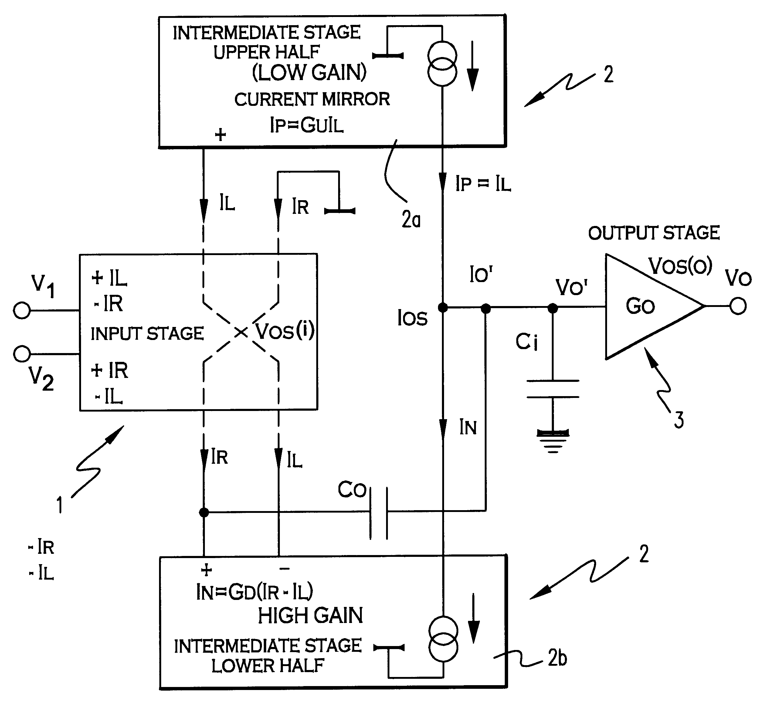
Referring to FIG. 3a, the main features of the new architecture proposed by the invention for an amplifier including an input stage 1, an intermediate stage 2 and an output stage 3 reside in: that the intermediate stage is a combination of two complementary class AB operating halves 2a and 2b; that the upper half 2a of said intermediate stage has a low limited and conveniently, but not necessarily controlled current gain G.sub.U ; and that the low half 2b of the same stage involves a high or very high current gain G.sub.D. Moreover, in the basic version of this amplifier, the input stage provides two pairs of antiphase output currents, I.sub.R and I.sub.L respectively, apt to be used to feed the halves 2a and 2b of the intermediate stage 2.

A first set of equations can be written for the scheme of amplifier possessing the architecture of FIG. 3a:

I.sub.R =I.sub.B +Ia.gtoreq.0 (24)

I.sub.L =I.sub.B -Ia.gtoreq.0 (25)

where I.sub.B is the quiescent current and la is the signal current. It ...


PUM


Abstract

In an amplifier with improved, high precision, high speed and low power consumption architecture, comprising an input stage (1), an intermediate stage (2) and an output stage (3), the intermediate stage (2) is provided by combining two complementary class AB operating halves (2a, 2b) which are driven by a complementary input stage, which is, in turn, class AB operating, one of said halves having a low limited current gain (GU), conveniently but not necessarily controlled, and the other one having a high or very high current gain (GD) which can, but not necessarily, be controlled. Suitably the input class AB operating input stage (1) of this amplifier provides two pairs or one pair of antiphase output currents (IR and IL), apt to be used to feed both halves (2a, 2b) of the intermediate stage.

Description

This invention refers to an amplifier with improved, high precision, high speed and low power consumption architecture, particularly suitable for a lot of applications.It is well known, in the field of analog electronics, that implementation of systems meeting requirements where high precision, low power consumption and high sped are simultaneous required is more and more requested. The main problem is to balance such requirements that, according to the known techniques, are in conflict with each other. Therefore, designers are forced to find the best trade off for their specific application.The requirements which designers should try to meet may be resumed as:DC precision (Low Input Offset Voltage, Vos, and Input Offset Currents, Ios, and Low Bias Currents, Ib);AC precision (Low Noise, Wide Power-Bandwidth and Low Distortion);High speed and Wide dynamic range;Low power consumptionThe main object of this invention is to provide innovative solutions, which substantially mitigate exis...

Claims


Application Information

Patent Timeline
Patent Type & Authority Patents(United States)
IPC IPC(8): H03F3/30H03F1/02
CPCH03F3/3067H03F3/3001
Inventor STOCHINO, GIOVANNI
Owner INFINEON TECH AG
Learn More